Co-simulating Verilog and SPICE circuits with QSPICE
If you are an engineer in any field related to electricity, in your degree I am pretty sure that you have simulated many electronic circuits, from linear circuits based on operational amplifiers to power circuits like switched-mode power supplies or DC/AC converters. Simulation is a crucial step in all our designs and thanks to tools like SPICE, it is also very easy to find an open-source simulation tool that reaches confident results. All is easy and free when we want to simulate electronic circuits, and nothing more than electronic circuits. When your design includes programmable devices like microcontrollers or FPGA, the simulations turn expensive. In the market, some tools can simulate electronic circuits and co-simulate a Verilog code. The word co-simulate is the key. Tools like PSIM or Simulink know how to simulate an electric circuit. They are excellent at solving differential equations, but they have no idea of Verilog simulation, so they need help. In both cases, the tools use Modelsim or Questa to simulate the Verilog code, and its simulator to simulate the electric circuit. Then, on each time step, Modelsim or Questa use the last outputs of the electric simulator as inputs for the Verilog code, generate the corresponding outputs, and send them to the electric simulator, which uses those outputs as inputs to the electric circuit, and finally, generate the outputs of the electric circuit. In the next step, the process is repeated until the total simulation time is reached.
If you are not a big tech company, you will notice that neither PSIM nor Simulink is cheap, and here we need to add the Modelsim license. As I said before, this will be expensive. Luckily, since 2022 Simulink accepts Vivado Simulator for Vivado co-simulation, which is very good news since the Vivado license is free for some parts.
I started the article by mentioning SPICE, an open-source tool for electric circuits, and we know different open-source Verilog simulators like Verilator, well is here where QSPICE arrived to save our money. The history behind QSPICE starts with LTSpice, designed by Mike Engelhardt, who years later moved to QORVO, where he designed QSPICE. According to its own words “QSPICE is what I would have written 25 years ago when I wrote LTspice had I known then what I know now”. Besides all the improvements in the electric simulation, this simulator uses Verilator to co-simulate electric circuits and Verilog code, which honestly, is great. In this article, we are going to dive into this feature.
When we open the QSPICE window, we will see a regular window to simulate electronic circuits, with the libraries on the left of the window, and a blank canvas where our circuit will be drawn.
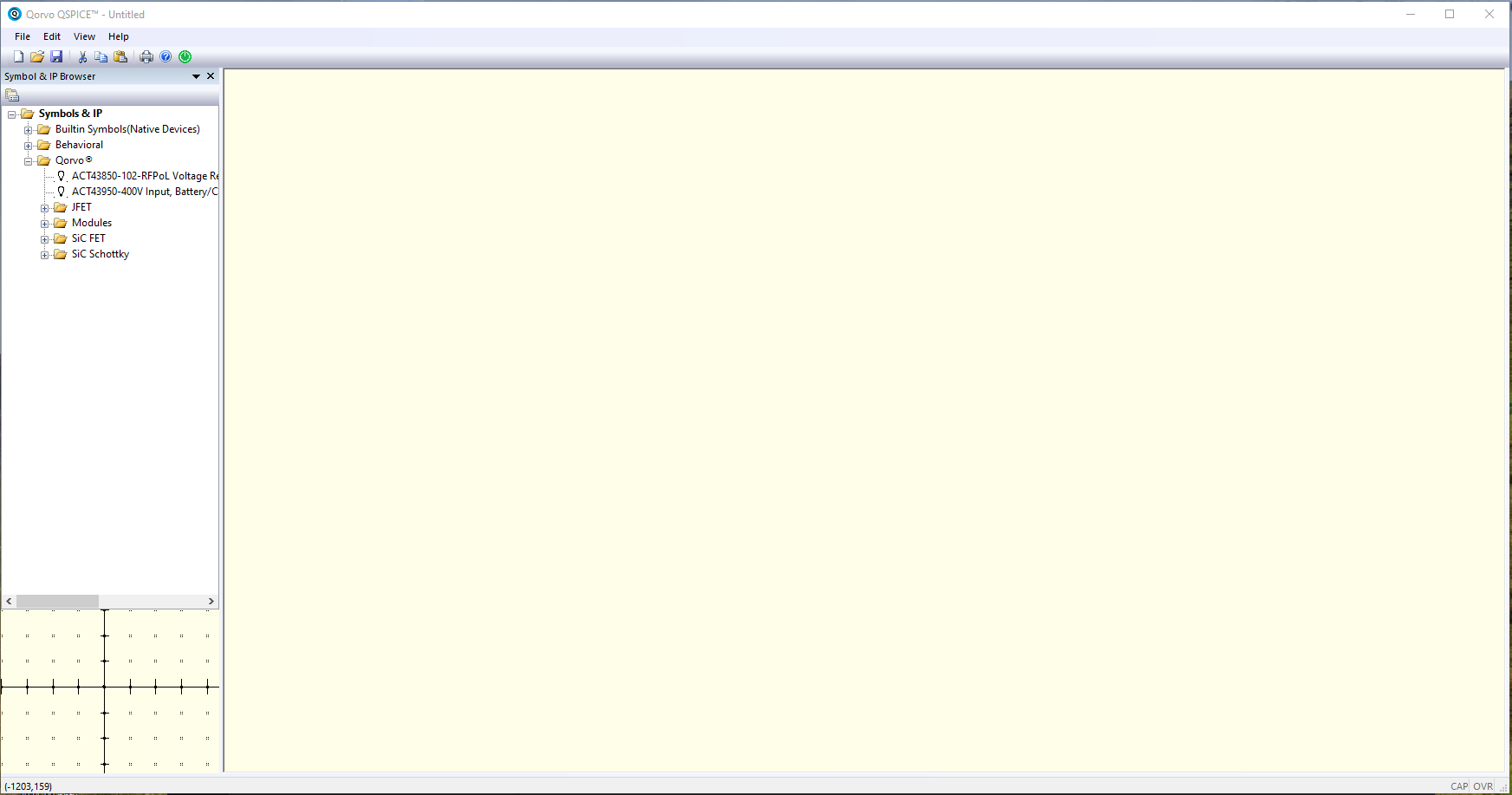
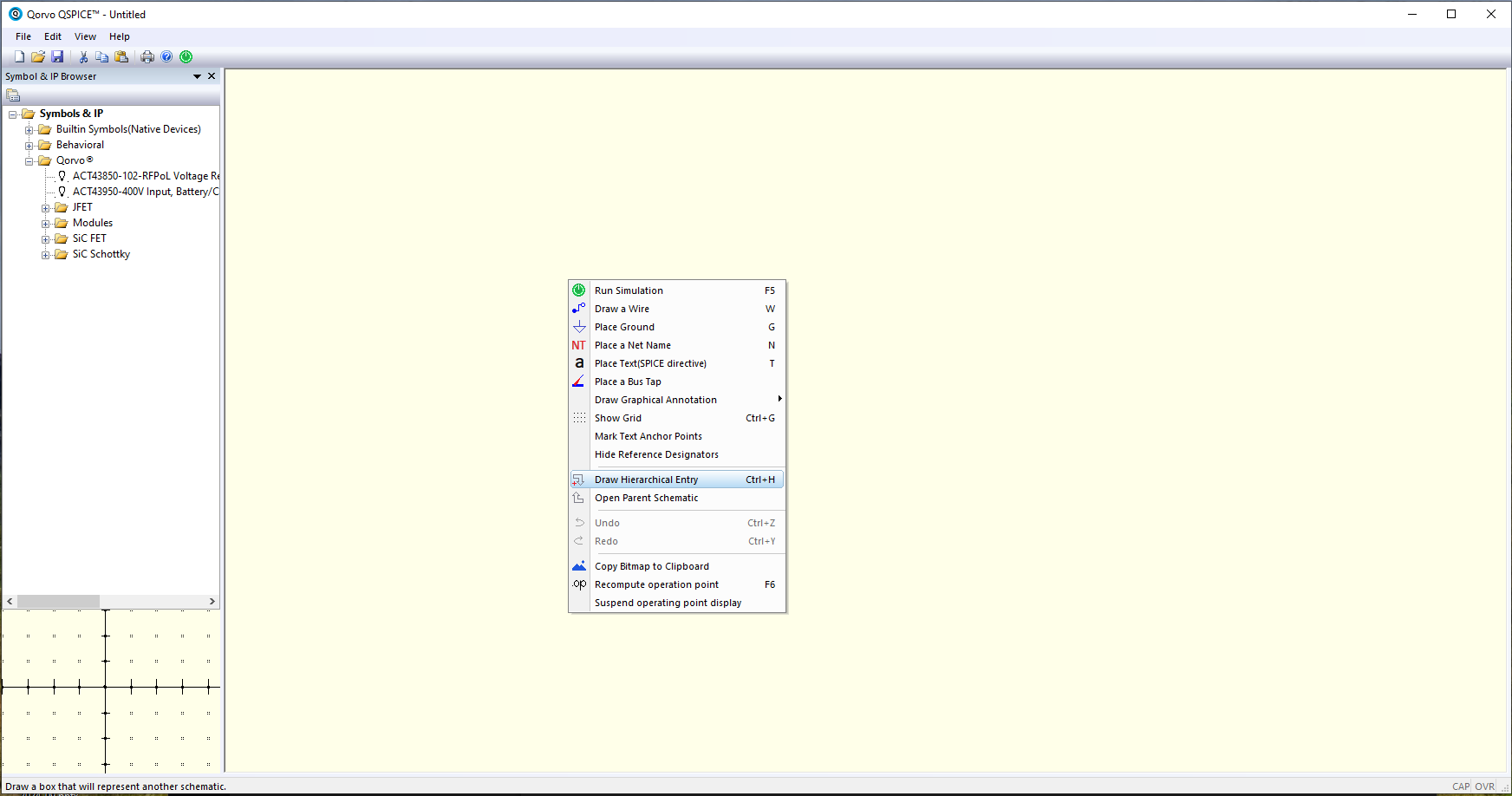
To insert Verilog or C++ code, we need to add first a Hierarchical Entry. To dot this by right click on the canvas, or pressing CTRL+H
Now we have to draw a rectangle. This rectangle will be the Verilog block.
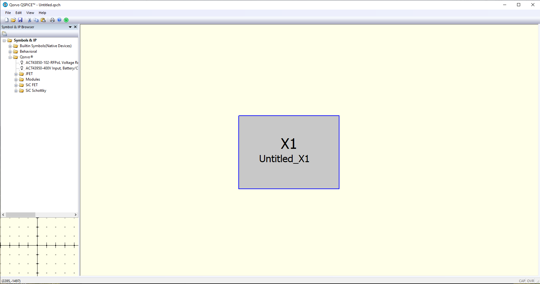
In the center of the rectangle, there is a name. This name will be the name of the Verilog file. QSPICE accepts hierarchical Verilog modules, but just the top one will be instantiated in the simulation.
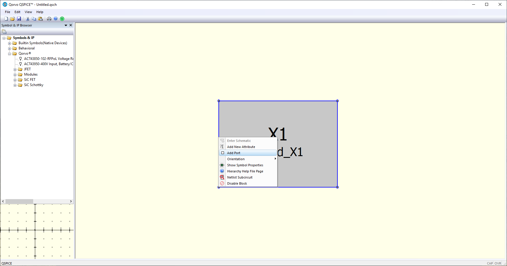
Now we can add all the ports of the top module. We can do this by right click on the rectangle, and clicking over Add Port. The name of the ports must match the ports declared in the Verilog module. Here we are going to add all the ports, including reset and clock.
Then, we are going to tell QSPICE that this block is indeed a Verilog module. To do this we need to change the Symbol type under the Symbol Properties menu. We can access this menu doing right-clicking on the rectangle.
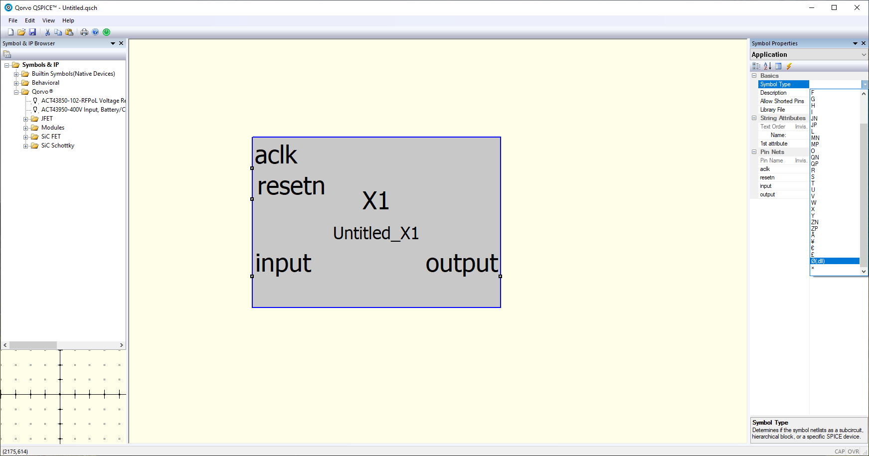
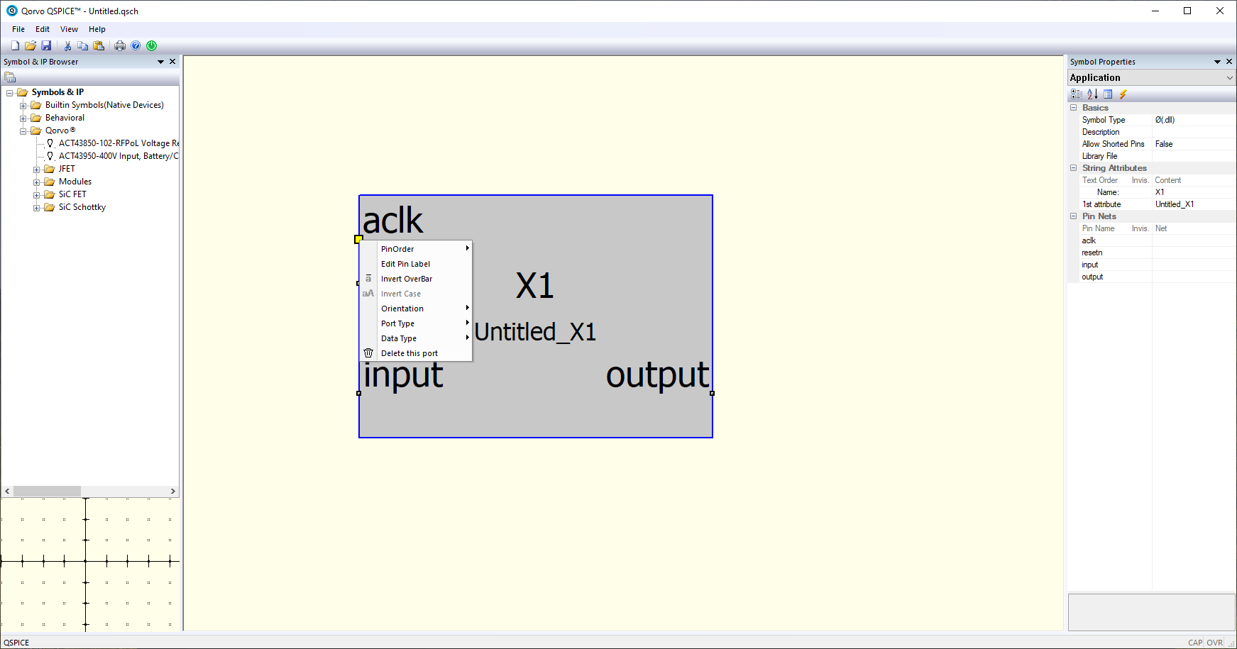
The symbol type will be Ø (.dll). Once the symbol type is set, we can configure each port. The configuration needed for each port is the Port Type, to configure the direction of the port, and the Data Type, to configure the width of the port. This configuration is very important to, later, see the simulation results in the scope, since the data will be represented according to this Data Type configuration.
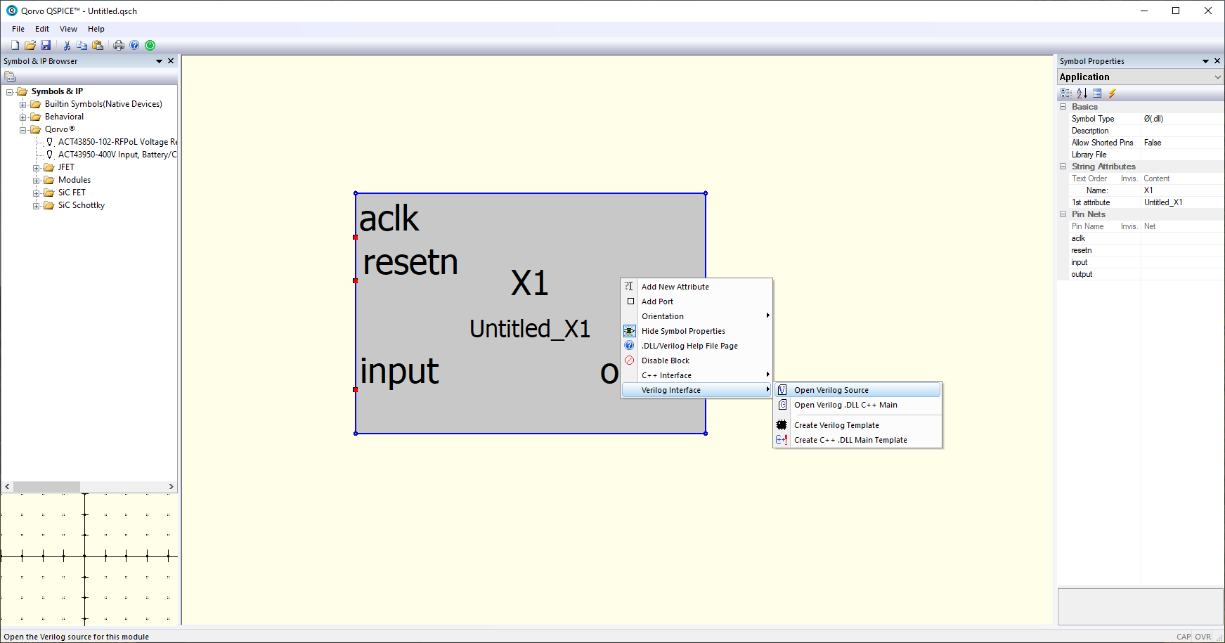
Now we are going to open the Verilog code. In the right-click menu, we can navigate to Verilog Interface > Open Verilog Source.
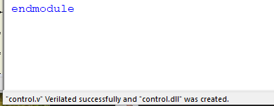
As I mentioned before, the name of the block is the name of the file that QSPICE will search in the same directory of the schematic file. When we have our Verilog code created, this code has to be sent to Verilator to generate the corresponding dll library. To do this, we can push F5 in the Verilog window, and, if all is fine, in the bottom-left corner we will see the message <MODULE NAME> Verilated succesfully and <MODULE NAME>.dll was created. If there is some error, a Verilator terminal window will be opened listing the errors found.
At this point, we can simulate Verilog code within an electric circuit, but it is not so easy. In my case, I have simulated the control of a Buck converter, writing in Verilog the PWM modulator and a simple PI controller. Both modules were simulated before, so I am sure that the modules are fine, but the simulation does not work as expected. The entire diagram I simulated was the next.
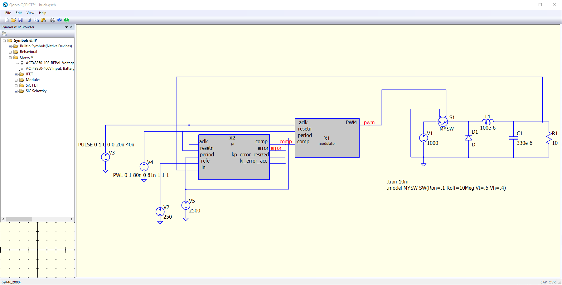
Let’s see what this diagram does. First, I generated the clock at 25 MHz using a voltage source. This voltage source is generated using a PULSE voltage source. The complete configuration is PULSE 0 1 0 0 0 20n 40n. The explanation of all the arguments of the voltage source is shown when we type PULSE in the voltage source configuration. For the reset, I used in this model a Piecewise Linear Voltage Source with the configuration PWL 0 0 80n 0 81n 1 1 1, which implements a 0V signal until the time 80ns, in which the voltage changes to 1 V. For the reference and the period of the PWM signal, I have used regular voltage sources. Then, the simulation will simulate 10 milliseconds, that are configured with the code .tran 10m. All these codes are standard, so you can find them in many guides.
The reason this simulation did not work as expected was the data types. QSPICE is very strict in the data type selection, and for now, you cannot select a signed signal with a width different from 32 to 64 bits. This has a simple solution, all my inputs and outputs with signals are set to 32 bits, and configured as Signed Integer. Even using this configuration, and after several hours of tests, I found that the internal operations of my PI controller, like the error, were not calculated correctly, and I suspect that it is due to the data type selected. Also, I had problems with the signal that connects the PI controller to the PWM generator, although it is a 32-bit unsigned signal.
At this point, and after missing so much the Data Type Conversion blocks of Simulink, I decided to do all the transformations between floats to bit vectors in Verilog, so I created a wrapper that instantiate both modules, the PI regulator and the modulator. The resulting diagram is the next.
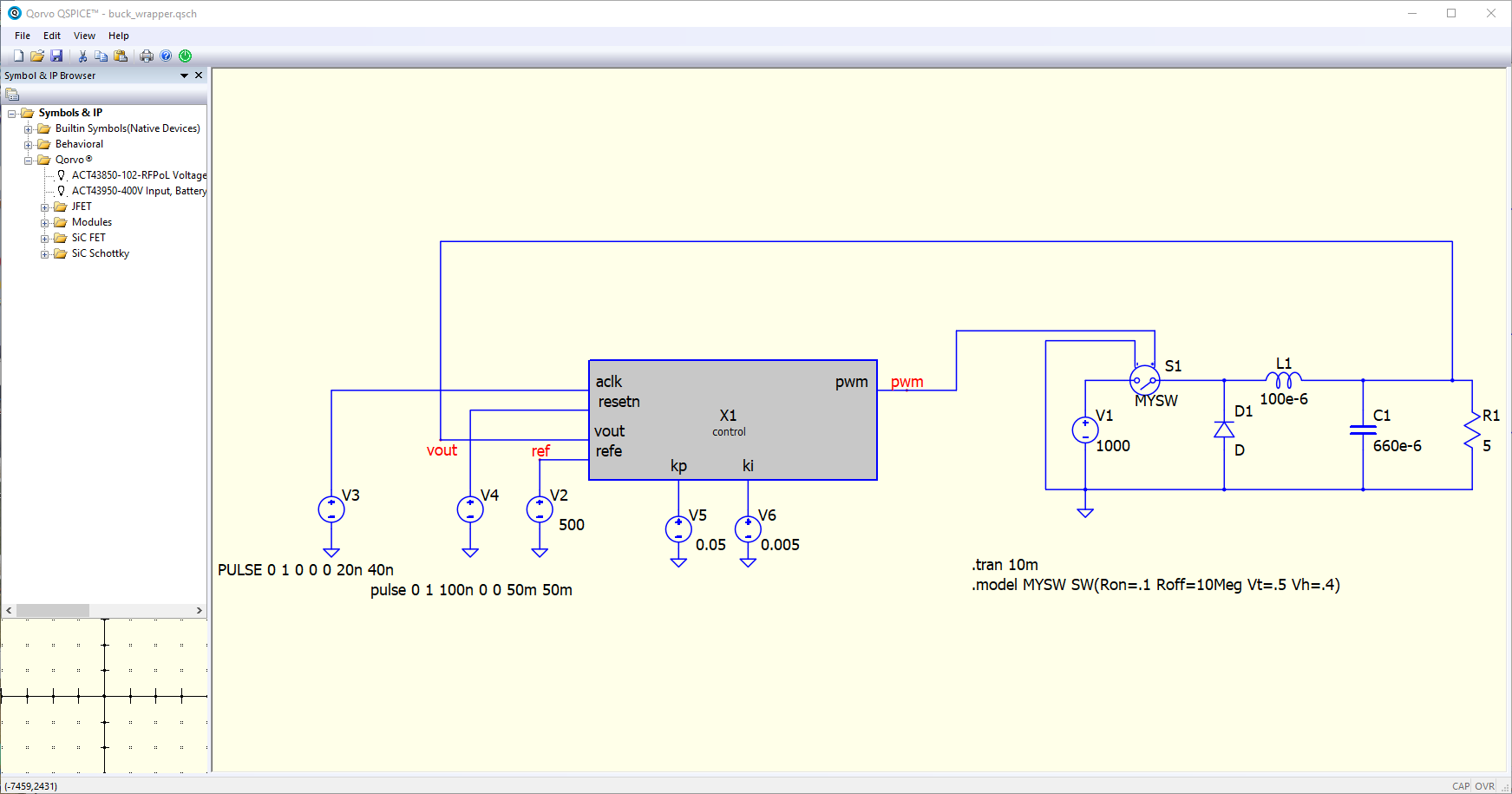
In the new wrapper generated, all the data inputs are of type real, and within this module, I perform the corresponding conversions. Also, this way I can avoid the problem in the out_pi signal since now it is done in Verilog. A short comment about the input real declaration. I use the AMD XST as a static analyzer, and the declaration input real is not valid in Verilog (.v) files, only in System Verilog (.sv) files, however, QSPICE only accepts Verilog files, so I had to live with several errors highlighted in VS Code.
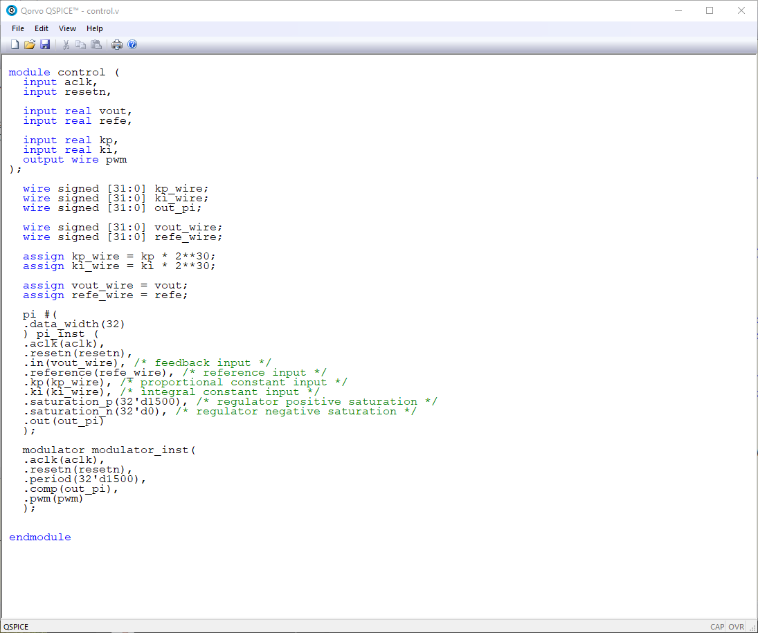
Finally, doing all these extra steps, I have been able to co-simulate my PI regulator and the PWM modulator written in Verilog, with an electrical circuit. I made different tests with different regulator constants, and here are the results.
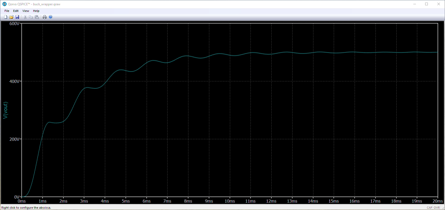
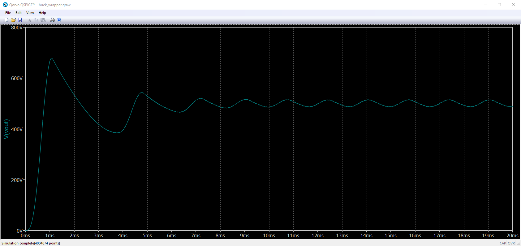
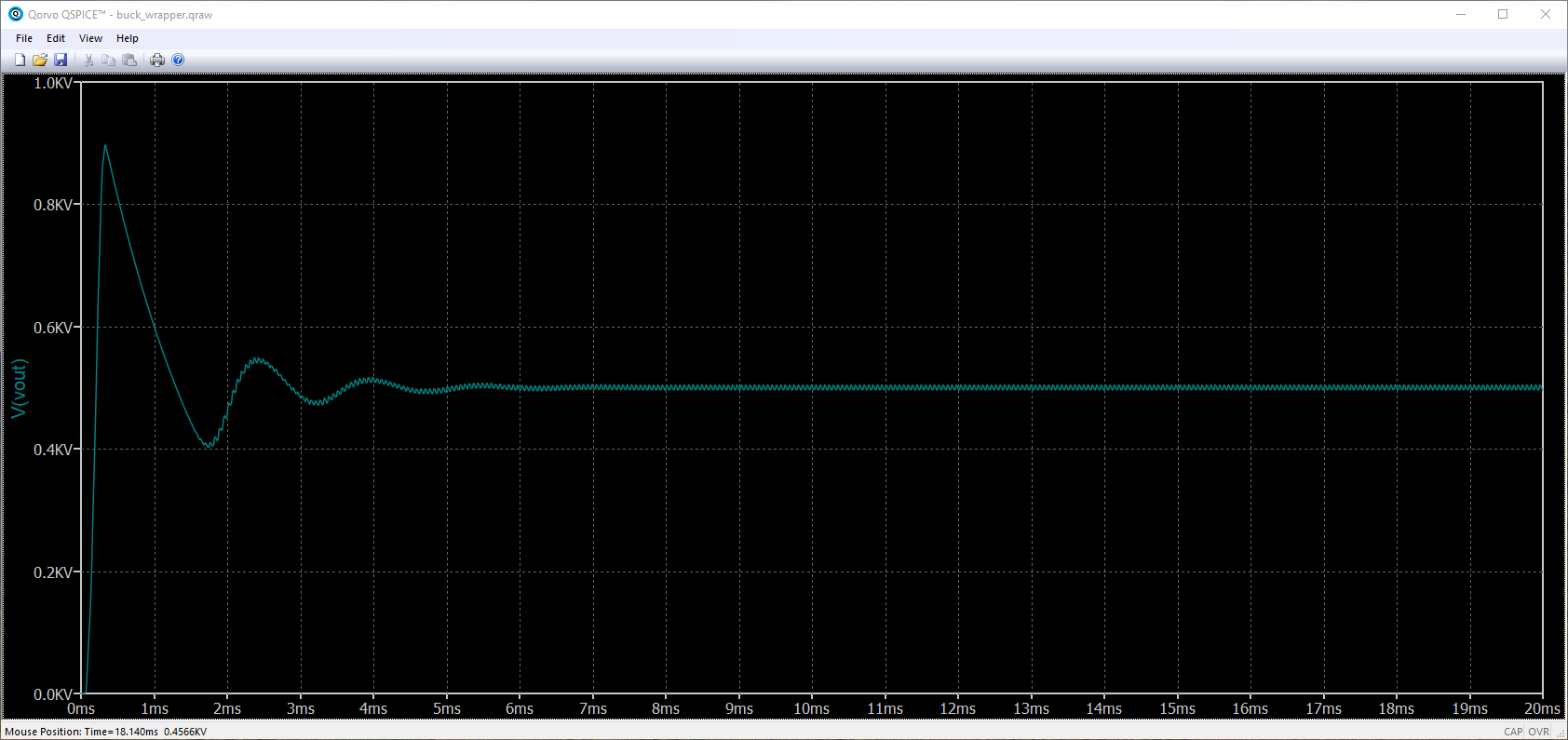
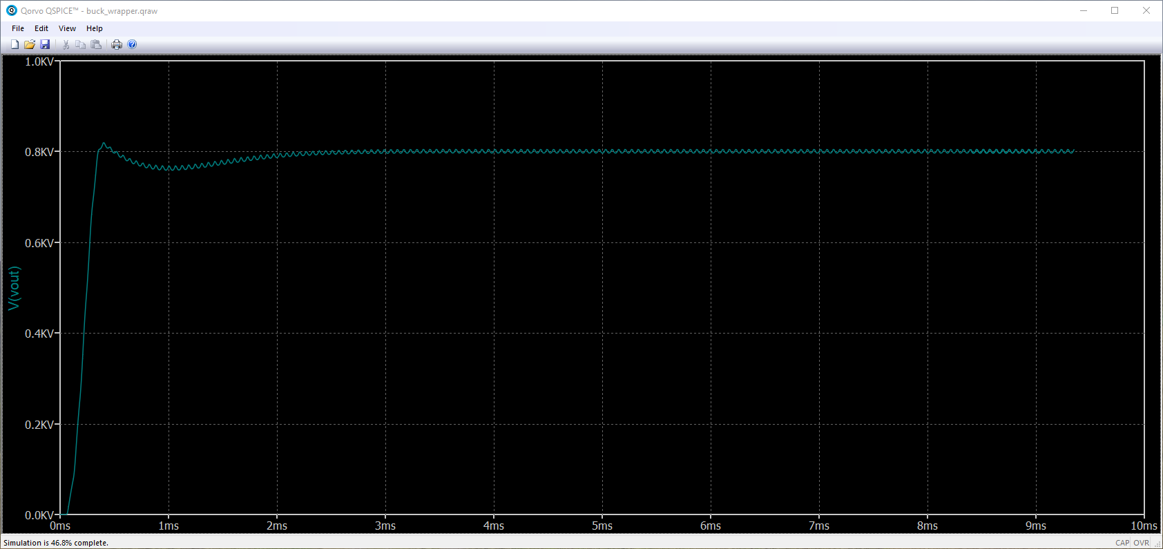
We can see that, in all cases the output reach the reference with more or less oscillations.
Let’s begin with the worst. QSPICE team has to work more on the data compatibility between Verilog and SPICE, adding some Data Type Converter blocks to the library will be great. Also, the fact that the .v code must be in the same directory as the SPICE files makes your workspace less comfortable. Would be great if the Verilog source could be selected with an Explorer window, this way we can keep the Verilog code and the SPICE code in separate folders. Despite this, it is great. I see this version as a first step, a really big first step. I am not going to say that it is the first no-cost tool that performs co-simulation with electric circuits and Verilog code because I am not 100% sure, but it is the first I tested, and works pretty well. I will try to keep you updated about this tool and will bring here newer versions.


