Creating a HDL Coder Support Package for Leonidas board
When we are working in any engineering field, probes of concept are essential in order to check if an idea can become a real product. The time spent in the probe of concept is crucial either to accept that probe of concept as a future product or to discard the idea finally. Unfortunately, FPGA and high-speed prototyping is something that, in many cases, is hard to achieve, however, there are tools in the market that could help us to reduce this time as much as possible. One of these tools is Matlab and HDL Coder.
In this blog we have many articles talk about HDL coder, but until now, we have used FPGA or SOC boards from the Matlab collection, and we have never created a new board to be used in the HDL Workflow Advisor. In this article, we are going to create a new Support Package for the Adiuvo’s Leonidas Board, and then we will use it to implement a Simulink model.
This article is divided into five different parts.
- Creating a Reference Design
- Registering the board
- Registering the Reference Design
- Using the board in HDL Coder WFA
- Configuring the design over JTAG
- Conclusions
Creating a Reference Design
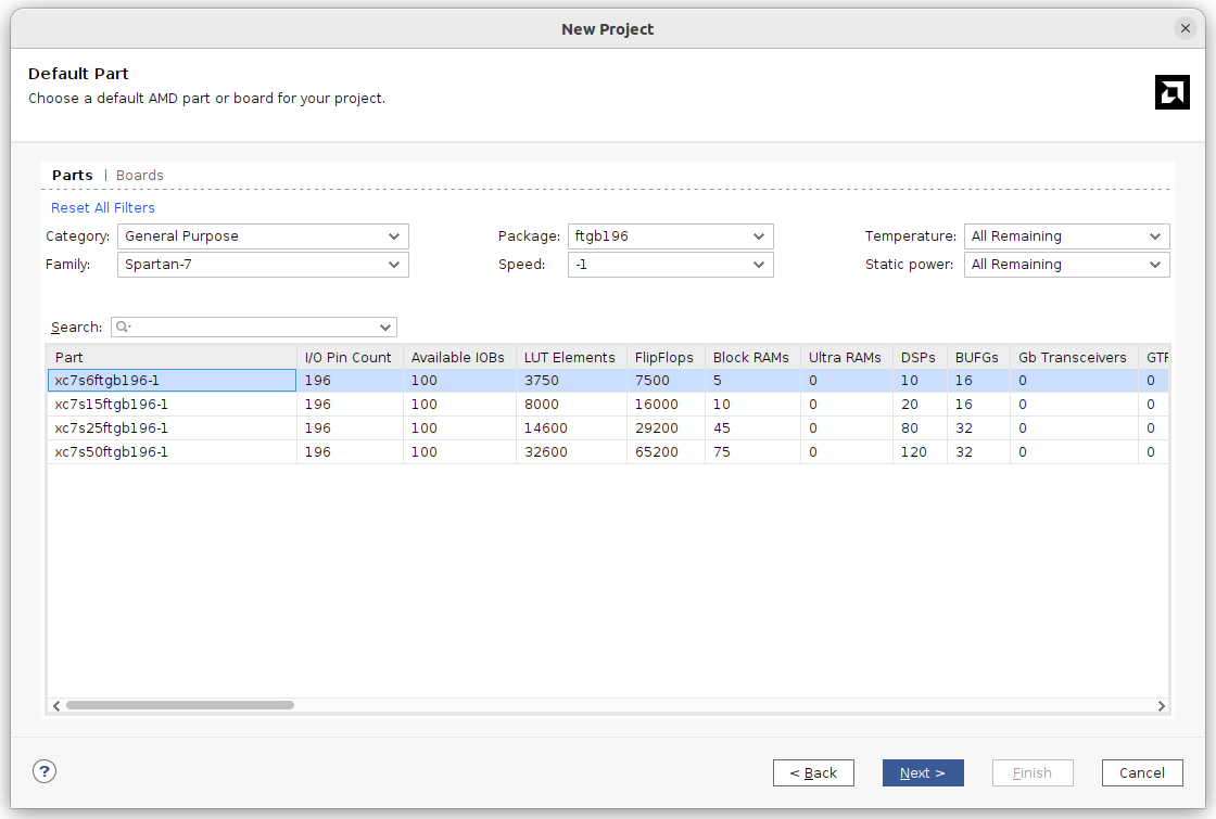
First of all, we need to create a Reference Design. This Reference Design consists of a base design that Matlab will use to add the generated IP Cores. This flow is pretty similar to the acceleration flow used by Vivado. To create the Reference Design, we need to create a Vivado project and select the part used in the Leonidas board, the xc7s6ftgb196-1.
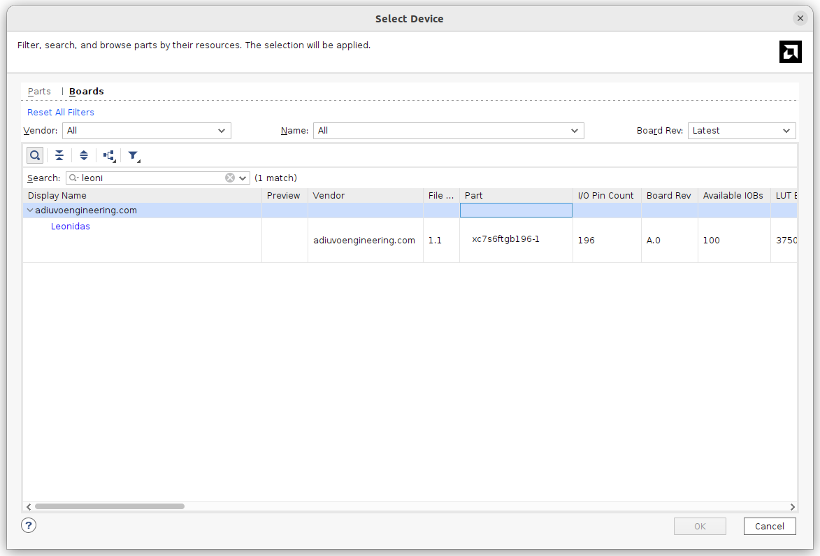
If you have the board files of the board, you need to find the board and select it.
Next, we are going to create a block design. From here, we can take two different ways. Since the Leonidas board has no Processing System, it is based on a Spartan7, we need to use to communicate the board to the host computer the JTAG. To make possible this communication, the design has to included an IP. This IP could be the JTAG to AXI Master from AMD, or the AXI Manager from Mathworks. The first one needs to be included in the Reference Design however, the second one, will be included by HDL Coder. Let’s start with the second one first using the AXI Manager from Mathworks.
First of all, as always, we need to create a block design.
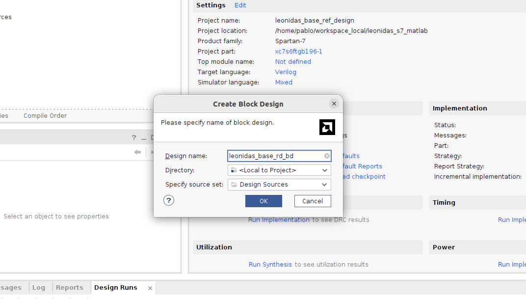
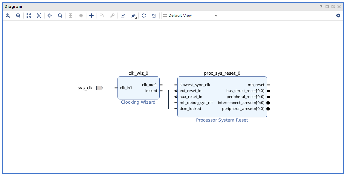
The Reference Design, in this case will include just a Clock source, which is a Clocking wizard, and a Processor System Reset to generate the reset signals for the IPs.
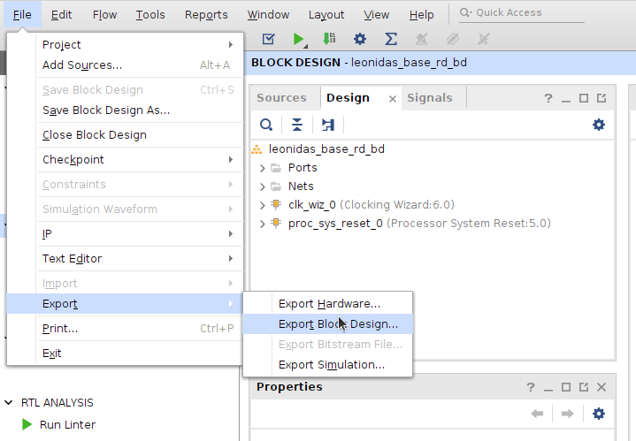
Now, we have to Validate the Block Design, and Export the block design as a tcl file.
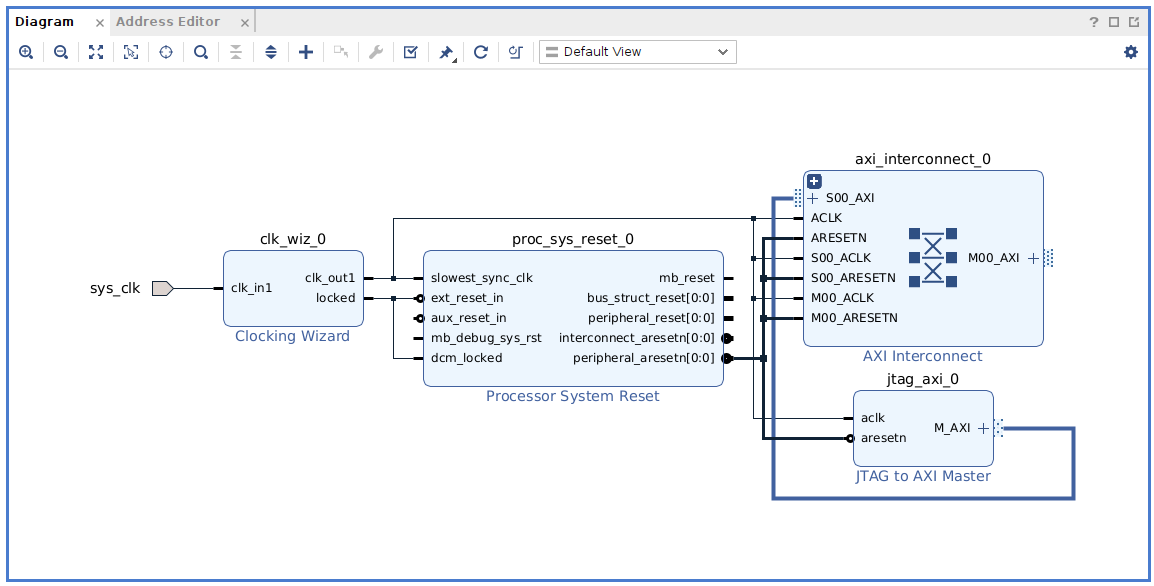
For the first flow, using the JTAG to AXI Master, we also need to add the JTAG to AXI Master IP, and an AXI Interconnect.
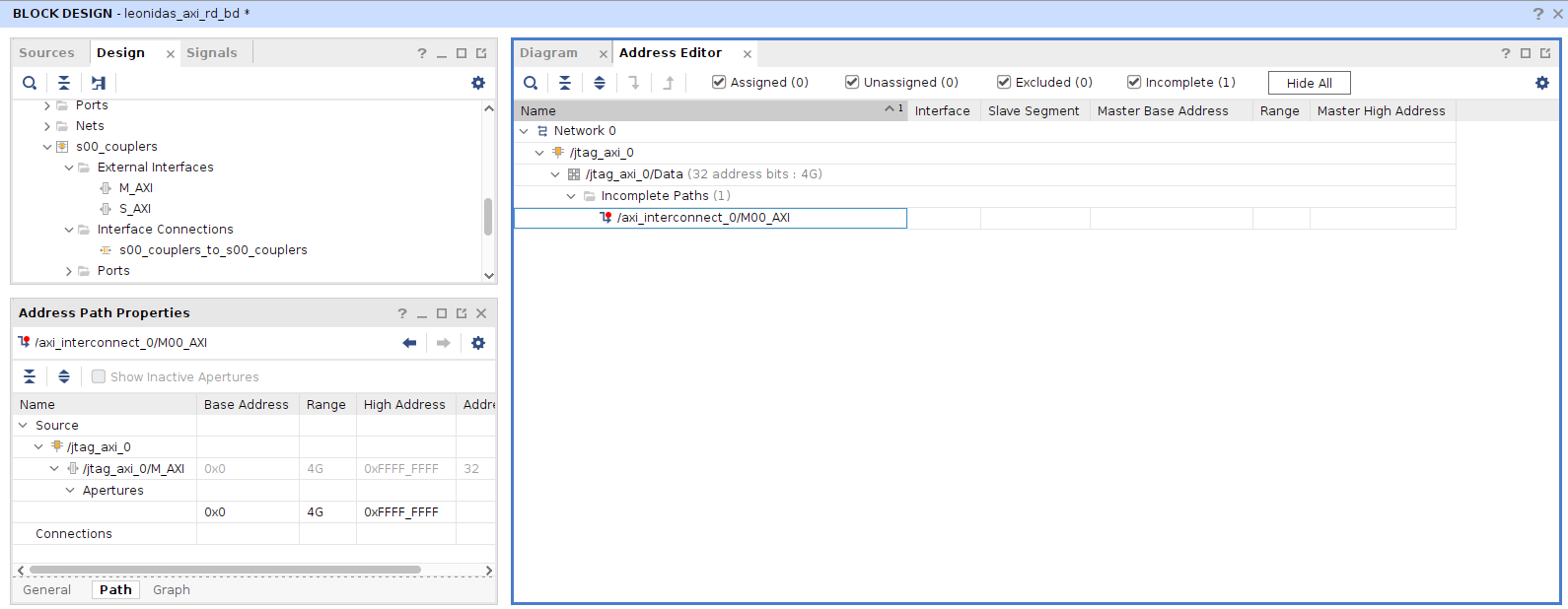
In this case, since we have al AXI Master in the Block Design, we can see the the tab Address Editor shows the AXI Networks.
Then, we just need to validate and export the Block Design.
Now, in the Reference Design we added a Clock input, which is connected to a physical port, so we need to constraint that port. We will do this with the
leonidas_base_rd_clk.xdc file.
set_property PACKAGE_PIN G11 [get_ports sys_clk]
set_property IOSTANDARD LVCMOS33 [get_ports sys_clk]
At this point, the Reference Design is ready. Notice that we have two different Reference Designs, the first one using the Mathworks AXI Manager, and the second one using the JTAG to AXI Master from AMD.
Registering the board
Now, we need to create the files to tell HDL Coder the capabilities of the board, and the resources available. The most important here is that the file tree needs to be the correct one. At the end of this section you can find the correct file tree, so here I am going to describe the corresponding files.
First of all, we are going to create a folder named as the name of the board, and using uppercase, in my case LEONIDAS. Now we need to create the hdlcoder_board_customization.m (the file names must be the same as I used). This file is very simple, and just includes a reference for the file that will describe the board. Again. the string LEONIDASregistration has to be written like this.
function r = hdlcoder_board_customization

r = {'LEONIDASRegistration.plugin_board'};

end
Then, we are going to create the plugin_board.m file. This file will describe the hardware of the board, from the part used, to the interfaces available. In the case of the Leonidas board, I added the LEDs, the push-buttons and the switches. The parameter hB.BoardName = 'Leonidas Embedded System Development Board'; will the the name that appears in the HDL Workflow Advisor, and must be the same in all the files of the Support Package.
function hB = plugin_board()
    % Board definition

    % Construct board object
    hB = hdlcoder.Board;

    hB.BoardName = 'Leonidas Embedded System Development Board';

    % FPGA device information
    hB.FPGAVendor   = 'Xilinx';
    hB.FPGAFamily   = 'Spartan7';
    hB.FPGADevice   = 'xc7s6ftgb196-1';
    %hB.FPGAPackage  = '';
    %hB.FPGASpeed    = '';

    % Tool information
    hB.SupportedTool = {'Xilinx Vivado'};

    % FPGA JTAG chain position
    hB.JTAGChainPosition = 1;

    %% Add interfaces

    % leds
    hB.addExternalIOInterface( ...
        'InterfaceID','Leds', ...
        'InterfaceType','OUT', ...
        'PortName','GPLEDS', ...
        'PortWidth',4, ...
        'FPGAPin',{'E11', 'M10', 'A10', 'D12'}, ...
        'IOPadConstraint',{'IOSTANDARD = LVCMOS33'});

    hB.addExternalIOInterface( ...
        'InterfaceID','PushButtons', ...
        'InterfaceType','IN', ...
        'PortName','PUSH', ...
        'PortWidth',4, ...
        'FPGAPin',{'M5', 'L5', 'N4', 'P5'}, ...
        'IOPadConstraint',{'IOSTANDARD = LVCMOS33'});

     hB.addExternalIOInterface( ...
        'InterfaceID','Switch', ...
        'InterfaceType','IN', ...
        'PortName','SWITCH', ...
        'PortWidth',4, ...
        'FPGAPin',{'A12', 'A13', 'B13', 'B14'}, ...
        'IOPadConstraint',{'IOSTANDARD = LVCMOS33'});


end
With these two filed we already have defined the board. Now we need to define the different Reference Designs.
Registering the Reference Design
Now it is time for the Reference Design. The Reference Design is the design that we are going to use as a base project, and for a board we could have different Reference Designs, for example, for the Leonidas board we could have a Basic Reference Design, with just the interfaces and peripherals of the board, and another one that includes a Motor control PMOD connected to J3. This second Reference Design will include a PWM signal, a motor direction signal…. Also, we could have a Reference Design with a Microblaze, so in this case we will use the Microblaze to communicate the board with the host. In out case, we have two different Reference Designs, the first one with just a Clock source and a Reset generator, and the second one with an AXI Master.
To define all the available Reference Designs, we need to create the hdlcoder_ref_design_customization.m file. This file just include a list of the avauilable Reference Designs. Again, the LEONIDASRegistration string can not be changed.
function [rd, boardName] = hdlcoder_ref_design_customization

rd = {'LEONIDASRegistration.vivado_base_2023_1.plugin_rd', ...
    'LEONIDASRegistration.vivado_base_axi_jtag_2023_1.plugin_rd' ...
     };

boardName = 'Leonidas Embedded System Development Board';
end
Now, we have to create the plugin_rd.m file for the different Reference Designs. The first one will be the Base system Reference Design. This file, since it is related to a Vivado Block Design, needs to include information about that block design as well as the Vivado version used. This is done with the parameters hdlcoder.ReferenceDesign('SynthesisTool', 'Xilinx Vivado'); and hRD.SupportedToolVersion = {'2023.1'};.
Also, since the Reference Design needs an xdc file for the clock constraints, the parameter hRD.CustomConstraints = {'leonidas_base_rd_clk.xdc'}; is also needed.
The parameter hRD.HasProcessingSystem = false; is used to tell Matlab that we are using an FPGA board instead of a SOC board, so it won’t create the interface files for the ARM.
Regarding the parameters hRD.AddMatlabAXIManagerParameter = true; and hRD.MatlabAXIManagerDefaultValue = 'JTAG';, they are related to the options available later in the HDL Coder Workflow Advisor. The step 1.2 of the WFA, will ask us how we are going to communicate the board with the host and will let us select whether we want the HDL Coder to add an AXI Manager or not. Remember that one of the Reference Designs we created already has a JTAG to AXI Master, but the other one just includes the Clock source and the Reset generator. For this second Reference Design we will let the users to select if they will need an AXI interface or not, and in case it will be needed the default way of communication will be JTAG.
Finally, we need to add the parameter hRD.addClockInterface to configure the Clock source and the Reset generator.
function hRD = plugin_rd()
    % Reference Design definition

    % Construct Reference Design object
    hRD = hdlcoder.ReferenceDesign('SynthesisTool', 'Xilinx Vivado');

    hRD.ReferenceDesignName = 'Base system';
    hRD.BoardName = 'Leonidas Embedded System Development Board';

    % Tool information
    hRD.SupportedToolVersion = {'2023.1'};

    % The part has not a PS
    hRD.HasProcessingSystem = false;

    % The user have not to select whether the design have AXI manager or
    % not
    hRD.AddMatlabAXIManagerParameter = true;
    hRD.MatlabAXIManagerDefaultValue = 'JTAG';


    hRD.addCustomVivadoDesign( ...
    'CustomBlockDesignTcl', 'leonidas_base_rd_bd.tcl' ...
    );
    %'VivadoBoardPart','adiuvoengineering.com:leonidas:part0:1.1');

    hRD.CustomConstraints = {'leonidas_base_rd_clk.xdc'};

    %% Add interfaces
    % add clock interface
    hRD.addClockInterface( ...
      'ClockConnection',   '/clk_wiz_0/clk_out1', ...
      'ResetConnection',   '/proc_sys_reset_0/peripheral_aresetn');

end
For the Reference Design that already includes the JTAG to AXI Master, named Base AXI JTAG Reference Design the plugin_rd.m file is very similar to the last one but with two differences. The first one, the parameter hRD.AddMatlabAXIManagerParameter is set now to false. This means that the HDL Workflow Advisor won’t ask us if we need to add an AXI Manager because we already have an AXI master in the design. And the second difference is related to this AXI MAster that we have added to the design. We need to add information about this AXI4 Lite interface, and this is done with the parameter hRD.addAXI4SlaveInterface.
function hRD = plugin_rd()
    % Reference Design definition

    % Construct Reference Design object
    hRD = hdlcoder.ReferenceDesign('SynthesisTool', 'Xilinx Vivado');

    hRD.ReferenceDesignName = 'Base system with JTAG to AXI_M';
    hRD.BoardName = 'Leonidas Embedded System Development Board';

    % Tool information
    hRD.SupportedToolVersion = {'2023.1'};

    % The part has not a PS
    hRD.HasProcessingSystem = false;

    % The user have not to select whether the design have AXI manager or
    % not
    hRD.AddMatlabAXIManagerParameter = false;
    hRD.MatlabAXIManagerDefaultValue = 'JTAG';

    hRD.addCustomVivadoDesign( ...
    'CustomBlockDesignTcl', 'leonidas_axi_rd_bd.tcl' ...
    );

    %'VivadoBoardPart','adiuvoengineering.com:leonidas:part0:1.1');

    hRD.CustomConstraints = {'leonidas_base_rd_clk.xdc'}

    %% Add interfaces
    % add clock interface
    hRD.addClockInterface( ...
      'ClockConnection',   '/clk_wiz_0/clk_out1', ...
      'ResetConnection',   '/proc_sys_reset_0/peripheral_aresetn');

    % add AXI4 and AXI4-Lite slave interfaces
    hRD.addAXI4SlaveInterface( ...
    'InterfaceConnection', '/axi_interconnect_0/M00_AXI', ...
    'BaseAddress',         '0x0000000000', ...
    'MasterAddressSpace',  'jtag_axi_0/Data');

end
With these two files, we already have all the files created. All these files have to be organized in a specific file tree. This file tree has to include different folders with the + suffix added. The entire file tree for the LEONIDAS folder is the next.
pablo@miercoles:~/workspace_local/leonidas_s7_Matlab/LEONIDAS$ tree
.
├── hdlcoder_board_customization.m
└── +LEONIDASRegistration
    ├── hdlcoder_ref_design_customization.m
    ├── plugin_board.m
    ├── +vivado_base_2023_1
    │   ├── leonidas_base_rd_bd.tcl
    │   ├── leonidas_base_rd_clk.xdc
    │   └── plugin_rd.m
    └── +vivado_base_axi_jtag_2023_1
        ├── leonidas_axi_rd_bd.tcl
        ├── leonidas_base_rd_clk.xdc
        └── plugin_rd.m

3 directories, 9 files
At this point, we are ready to use this support package in a HDL Coder workflow.
Using the board in HDL Coder WFA
Just after opening Matlab, we need to set the Vivado path. For the Matlab 2024a version, the Vivado-compatible version is 2023.1, and that is the same version I used to create the Reference Designs. Also, we need to add to the Matlab path the LEONIDAS folder. We can do this with these two commands.
hdlsetuptoolpath('ToolName','Xilinx Vivado','ToolPath','/media/pablo/ext_ssd0/xilinx/Vivado/2023.1/bin/vivado');
addpath(genpath('LEONIDAS'))
Now we are going to use a very simple example of HDL Coder Workflow Advisor, the hdlcoder_led_blinking. This example is included in the HDL Coder package installation, so we just need to use the command open_system to open the Simulink Model.
open_system('hdlcoder_led_blinking');
As I said before, this model is very simple. It generates an 8-bit counter, and conenct the output of the counter to outputs, that will be conencted to LEDs in the board.
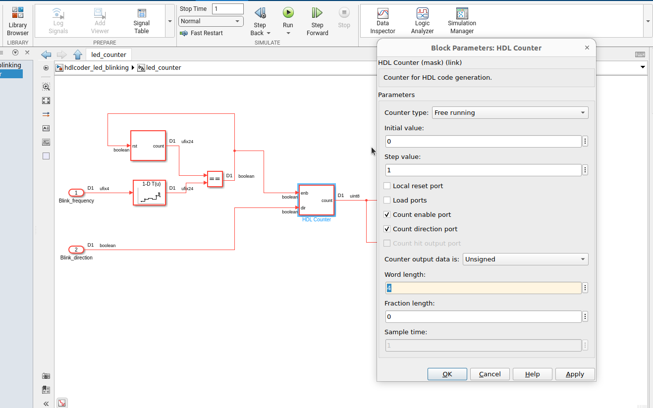
The counter used in the example is an 8-bit counter, but the Leonidas Board just have four LEDs, so we need to change the length of the counter to four. We can do this navigating to into the led_counter block, and changing the value Word length in the HDL Counter block.
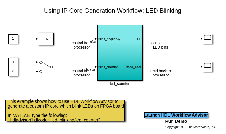
Now we are ready to launch the HDL Coder Workflow Advisor by clicking on the Launch HDL Workflow Advisor button of the model.
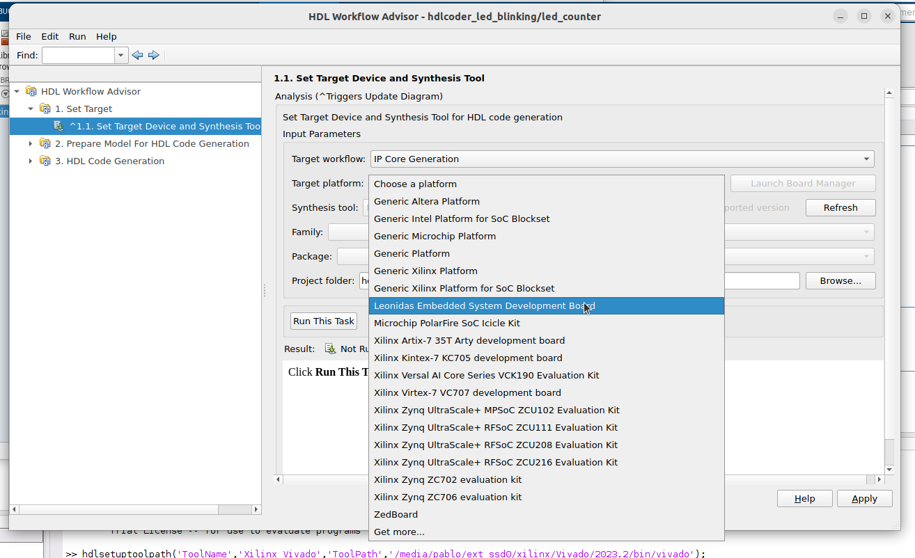
First, in the Set Targer Device and Synthesys Tool section, we need to select the Target workflow as IP Core Generation and set the Target platform as Leonidas Embedded System Development Board. The rest of the fields will be auto completed by the tool according the configuration of the board. now, we can click on Run This Task to continue.
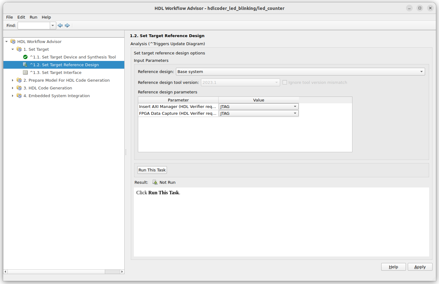
Now we need to set the Reference Design used. Remember that we have two different Reference Designs. Of we select the Base system, the Reference Design with just the Clock source and the Reset generation, the option Insert AXI Manager will be visible, however, if we select the Reference Design Base AXI JTAG Reference Design, this option will be hidden and forced to false.
Since the model we are going to implement needs an AXI Interface to configure the Blink Frecuency and the Blink Direction, we are going to select JTAG manually in the field Insert AXI Manager.
Now we are going to connect the board interfaces to the model interfaces. For the Blink_frequency, Blink_direction and the read_back, we are going to select AXI4-lite. These parameters of the design will be configurable or readable through the AXI interface. For the LED output port, we can select the Pucs-buttons, the Switches, or the LED of the board. Surprisingly the LEDs will be connected to this interface. Now we can go ahead by clicking on Run This Task.
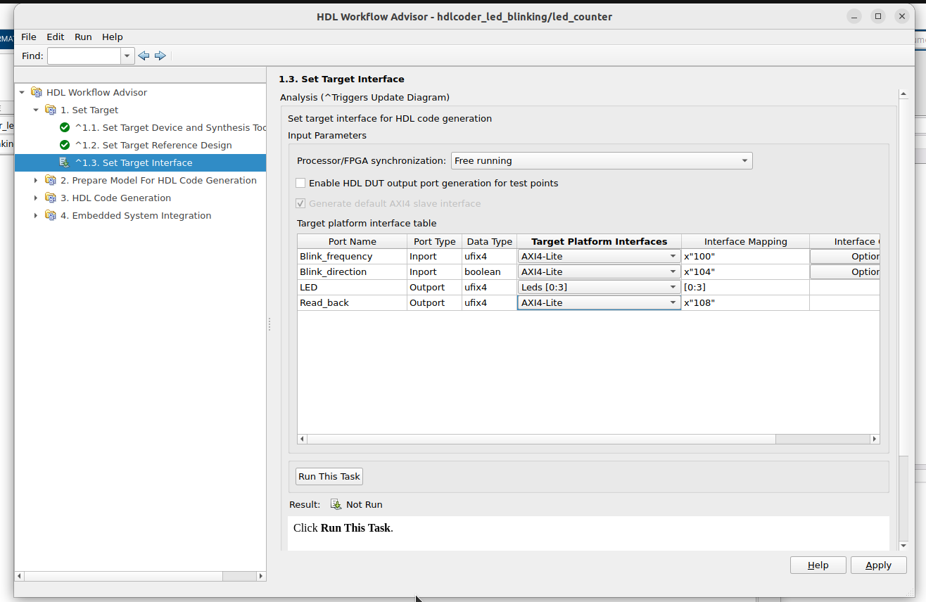
Now we can jump to step 3.2 to generate the RTL for the IP core. When this step is executed, the report will be opened to check how HDL Coder has implemented the model.
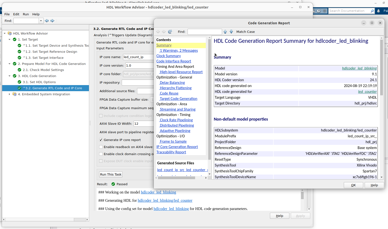
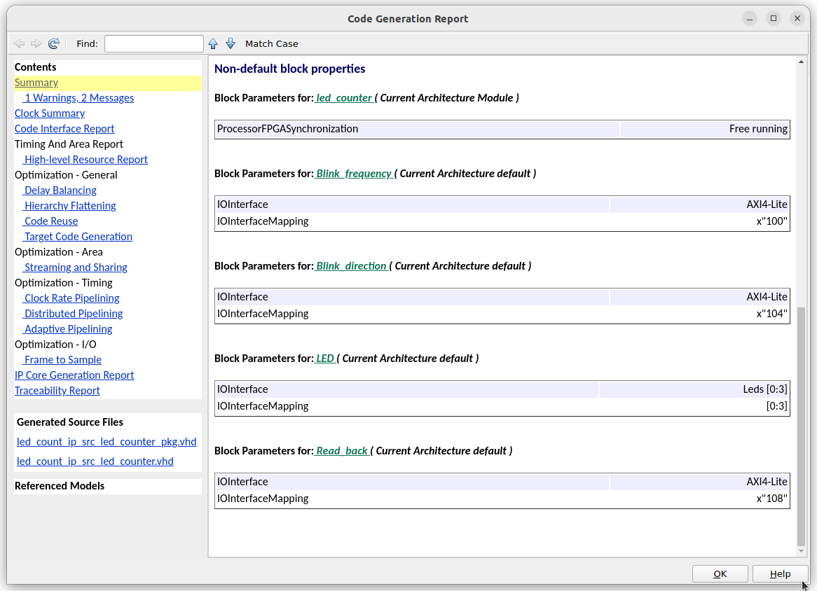
An important part of this report is where we can find the AXI addresses of each port. These addresses must be the same configured in the step 1.2.
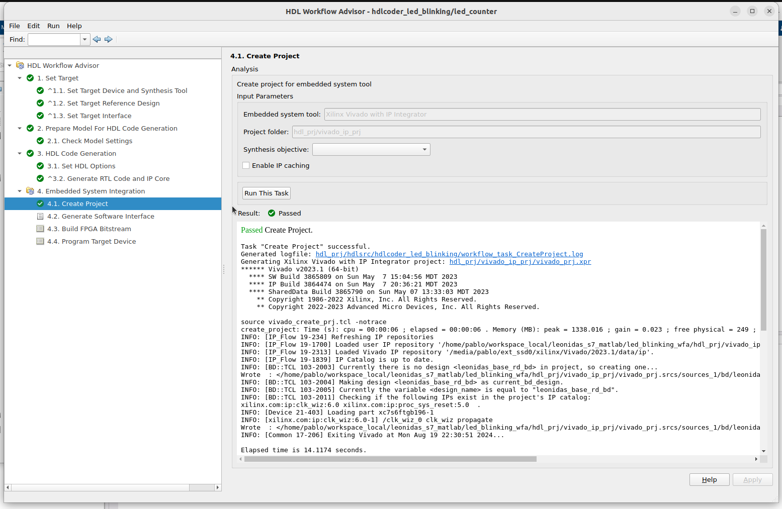
Now, the next step is to generate a Vivado project. This project will include the Reference Design and the IP Core created by HDL Coder with all the connections.
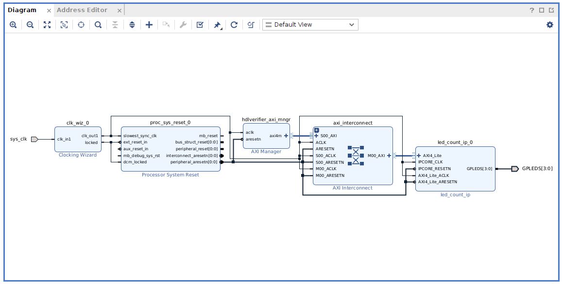
If we execute the workflow for both Reference Designs we can see the differences between the Block Designs. For the Base system Reference Design, where we just have the Clock source and the Reset generator, and we have configured the HDL Workflow Advisor to add an AXI manager, we can see how, indeed, HDL Coder has added the AXI Manager IP besides an AXI INterconenct and the led_count_ip, which is the IP of the Simulink model.
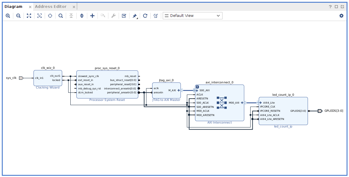
On the other side, for the Reference Design Base AXI JTAG Reference Design, HDL Coder just added the led_count_ip, since the Reference Design already had an AXI Master.
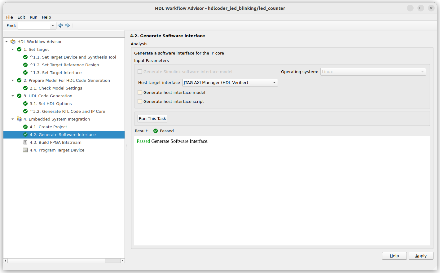
The next step in the HDL Workflow Advisor is the generation of the Software Interface. In this case, we are using a board without a Processing System, so the interface generated by HDL Coder will be just a Matlab script.
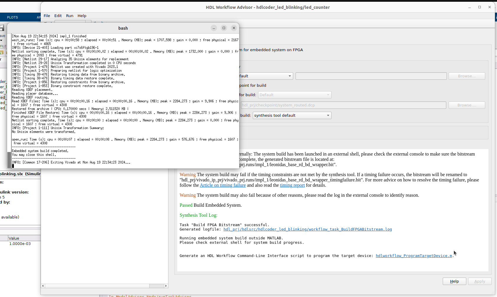
Now, we can build the project in the step 4.3.
And finally, configure the FPGA in the step 4.4.
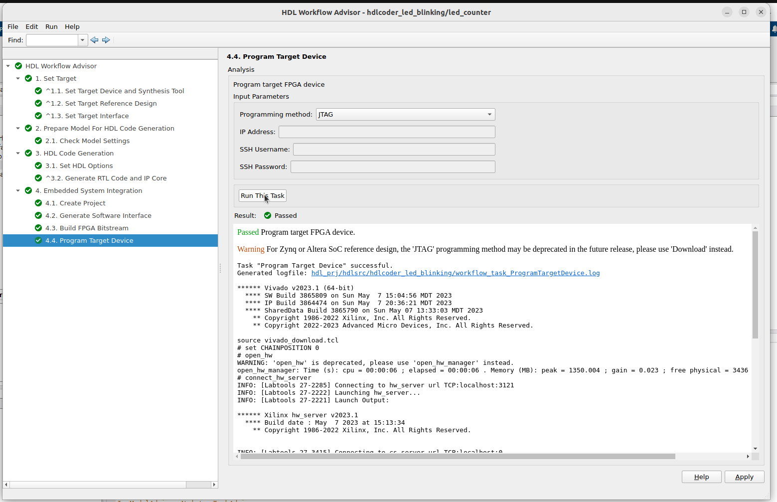
The Leonidas board is now configured with the design created, and the LEDs will blink. The next is to talk with the board.
Configuring the design over JTAG
Again, we need to separate the steps for the two different block designs. Matlab can write AXI registers only if our design has an AXI Manager, so this will only work with the Base system Reference Design.
Within Matlab, we need to execute the next commands to write an AXI register. In this case, we are going to change the Blink_frequency register, in the address 0x104.
> mem = aximanager('Xilinx')

mem =

   aximanager with properties:

            Vendor: 'Xilinx'
     JTAGCableName: 'auto'

> writememory(mem,0x100,2);
To read a register we can use the command readmemory.
> rd_val = readmemory(mem,0x108,1)

rd_val =

   uint32

    13
For the Base AXI JTAG Reference Design, where we have a JTAG to AXI Master, we can do the same, but using Vivado instead. We are going to open the Hardware manager of Vivado, connect the board and a hw_axi_1 peripheral will be detected on the board.
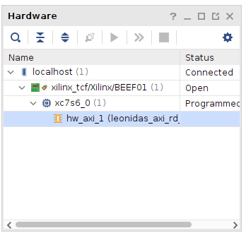
Now, with TCL commands we can create AXI transactions. First we are oing to reset the hw_axi_1 peripheral.
> reset_hw_axi [get_hw_axis hw_axi_1]
Now, to write an AXI register, we need to create the transaction with the command create_hw_axi_txn.
> create_hw_axi_txn write_txn [get_hw_axis hw_axi_1] -type WRITE -address 0x100 -len 1 -data 0x00000001 -force
write_txn
And then execute the transaction with the command run_hw_axi.
> run_hw_axi [get_hw_axi_txns write_txn]
INFO: [Labtoolstcl 44-481] WRITE DATA is: 0x00000001
To execute a reading, we need to create a new transaction, this time with the argument -type READ, and execute it.
> create_hw_axi_txn read_rxn [get_hw_axis hw_axi_1] -type READ -address 0x108 -len 1
read_rxn
> run_hw_axi [get_hw_axi_txns read_rxn]
INFO: [Labtoolstcl 44-481] READ DATA is: 00000002
Conclusions
This example has been too simple to see all the power of this flow, but think that, with more complex Reference Designs that include some external HW, we can test different probes of concept very fast, and see results in just a few hours. To finish, something that caught my attention is the amount of resources used for each implementation. Using the Reference Design Base AXI JTAG Reference Design, where a JTAG to AXI Master IP is included, the resources used are the next.
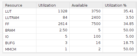
However, for the Base design, where Matlab has included its AXI Manager, the resources used have been significantly reduced.
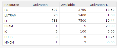
This is very important when we are using small parts like the XC7S6 used in the Leonidas board. The next steps are adding a Microblaze IP to use it to communicate the host and the board and create another Reference Design with external HW connected to the board.


