Vitis acceleration flow and the KR260.
Since a few years ago, FPGA are widely used for acceleration. In this blog, we have talked about how we can connect an FPGA to the PCI socket of our computer, and interchange data between the processor and the FPGA. SOCs, give us the chance to have in a single chip a processor (CPU) and an FPGA, so we can say that a SOC like Zynq MPSOC is a computer with an FPGA attached, and, in the same way, as happens with computers, we can use the FPGA to accelerate application which runs on the CPU, but in this case, we don’t need external interfaces to communicate the CPU and the FPGA. Using a SOC we have inside several AXI interfaces to communicate both domains very efficiently.
Using a single chip from a single manufacturer has some advantages, and the most important is that the application running on the CPU and the acceleration kernel which is implemented on the FPGA are developed using a single Vitis flow. And we will see how we are going to describe an application on Vitis, and then this application is translated into an RTL code which is configured on the FPGA in the deployment stage.
The steps we need to follow in this Vitis acceleration flow are quite similar to a regular Zynq MPSOC design but has some important differences. The first one is that the hardware design we need to have when we build Petalinux is not completed, and it will be completed by Vitis when the acceleration application is developed. Is this related with some kind of partial reconfiguration? Absolutely no, since the design is not written on the FPGA uncomplete. We are going to give to Vitis a Design with some open interfaces which it will use to connect the kernel, sounds interesting?
For this post, I going to use the KR260 Robotics Starter Kit, which is based on a Kria K26 SOM.
First of all, we need to update the Kria SOM boot image.
Updating the boot image of the KR260
Kria SOMs are configured to read the QSPI memory in the first place, which is written with a factory pre-programed firmware. Secondly, the QSPI boot firmware boots from the eMMC/SD card. To update this firmware have to execute an application. This application is available on Petalinux, but also on the Ubuntu for Kria SOMs, which is the option I will take. So we can go to the Ubuntu download page. To install Ubuntu on an SD card, we can follow the instruction from Ubuntu.com.
While we are downloading Ubuntu, we can also download the new BIN file for the QSPI memory from the Xilinx Wiki.
When the SD card is ready, insert the SD card into the SD card slot on the KR260 kit, and connect an Ethernet cable in the top-right Ethernet connector, and finally connect the power supply.
A minute later Linux is running, so we can connect the board using SSH. In the first connection, Ubuntu will ask us to change the password.
Once the password is changed, we can stablish the SSH connection and send the new .BIN file to the Kria SOM using scp.
~/Downloads$ scp ./BOOT_xilinx-k26-starterkit-v2022.1-09152304_update3.BIN [email protected]:/home/ubuntu
[email protected]'s password:
BOOT_xilinx-k26-starterkit-v2022.1-09152304_u 100% 2555KB  10.6MB/s   00:00
Now, on the Kria SOM, we can check tht the file is received.
ubuntu@kria:~$ ls
BOOT_xilinx-k26-starterkit-v2022.1-09152304_update3.BIN  snap
Now, using the instruction xmutil bootfw_update we can update the boot firmware of the QSPI memory.
ubuntu@kria:~$ sudo xmutil bootfw_update -i ./BOOT_xilinx-k26-starterkit-v2022.1-09152304_update3.BIN
[sudo] password for ubuntu:
Marking last booted image as bootable
Reading Image..
Marking target image non bootable
Writing Image..
Marking target image as non bootable and requested image
./BOOT_xilinx-k26-starterkit-v2022.1-09152304_update3.BIN updated successfully
Creating a Petalinux base project.
Once the firmware of the QSPI memory is updated, we are going to create a base Petalinux project for the boards using its BSP.
In my case, I am using Ubuntu 22.4, which is not compatible with Petalinux 22.2, so I used a virtual machine for this project.
First of all, we need to execute the file settings.sh of Petalinux to have available all the commands.
pablo@ubuntu2004:~/petalinux/2022.2$ source settings.sh
PetaLinux environment set to '/home/pablo/petalinux/2022.2'
WARNING: /bin/sh is not bash!
bash is PetaLinux recommended shell. Please set your default shell to bash.
WARNING: This is not a supported OS
INFO: Checking free disk space
INFO: Checking installed tools
INFO: Checking installed development libraries
INFO: Checking network and other services
WARNING: No tftp server found - please refer to "UG1144 2022.2 PetaLinux Tools Documentation Reference Guide" for its impact and solution
Then, we are going to create a new Petalinux project using the BSP available on the Xilinx Download page.
pablo@ubuntu2004:~/kr260_ptlnx_base$ petalinux-create -t project -s /media/sf_data_fpga_prj/xilinx-kr260-starterkit-v2022.2-10141622.bsp --name kr260_base
INFO: Create project: kr260_base
INFO: New project successfully created in /home/pablo/kr260_ptlnx_base/kr260_base
Now directly we can build the Petalinux image.
pablo@ubuntu2004:~/kr260_ptlnx_base/kr260_base$ petalinux-build
[INFO] Sourcing buildtools
[INFO] Building project
[INFO] Sourcing build environment
[INFO] Generating workspace directory
INFO: bitbake petalinux-image-minimal
NOTE: Started PRServer with DBfile: /home/pablo/kr260_ptlnx_base/kr260_base/build/cache/prserv.sqlite3, Address: 127.0.0.1:45173, PID: 5458
Loading cache: 100% |                                           | ETA:  --:--:--
Loaded 0 entries from dependency cache.
Parsing recipes: 100% |##########################################| Time: 0:01:29
Parsing of 4461 .bb files complete (0 cached, 4461 parsed). 6497 targets, 567 skipped, 1 masked, 0 errors.
NOTE: Resolving any missing task queue dependencies
NOTE: Fetching uninative binary shim file:///home/pablo/kr260_ptlnx_base/kr260_base/components/yocto/downloads/uninative/126f4f7f6f21084ee140dac3eb4c536b963837826b7c38599db0b512c3377ba2/x86_64-nativesdk-libc-3.4.tar.xz;sha256sum=126f4f7f6f21084ee140dac3eb4c536b963837826b7c38599db0b512c3377ba2 (will check PREMIRRORS first)
Initialising tasks: 100% |#######################################| Time: 0:00:09
Checking sstate mirror object availability: 100% |###############| Time: 0:01:30
Sstate summary: Wanted 3704 Local 0 Network 3101 Missed 603 Current 0 (83% match, 0% complete)
WARNING: k26-starter-kits-1.0-r0 do_configure: Using fpga-manager.bbclass requires fpga-overlay MACHINE_FEATURE to be enabled
Currently  1 running tasks (3705 of 3705/9129 of 9261)  98% |################# |
0: linux-xlnx-5.15.36+gitAUTOINC+19984dd147-r0 do_compile - 1m7s (pid 107169)
When the building is finished, we can package the image and prepare the image to be written into an SD card using wic format.
pablo@ubuntu2004:~/kr260_ptlnx_base/kr260_base$ petalinux-package --boot --u-boot --force
pablo@ubuntu2004:~/kr260_ptlnx_base/kr260_base$ petalinux-package --wic --images-dir images/linux/ --bootfiles "ramdisk.cpio.gz.u-boot,boot.scr,Image,system.dtb,system-zynqmp-sck-kr-g-revB.dtb" --disk-name "sda"
Finally, using the dd application, write the image into the SD card.
pablo@ubuntu2004:~/kr260_ptlnx_base/kr260_base/images/linux$ sudo dd if=petalinux-sdimage.wic of=/dev/sdb bs=4M status=progress
[sudo] password for pablo:
6442450944 bytes (6,4 GB, 6,0 GiB) copied, 329 s, 19,6 MB/s
1536+1 records in
1536+1 records out
6442455040 bytes (6,4 GB, 6,0 GiB) copied, 329,004 s, 19,6 MB/s
Once we have the SD card ready, insert the SD card into the KR260, and if all is OK, Petalinux will start. We can connect to the board using SSH.
pablo@friday:~$ ssh [email protected]
The authenticity of host '192.168.1.135 (192.168.1.135)' can't be established.
RSA key fingerprint is SHA256:/lD08NZwXDVo26u3qWR/SxTYbA92HHJG/r+RiRtYgKo.
This key is not known by any other names
Are you sure you want to continue connecting (yes/no/[fingerprint])? yes
Warning: Permanently added '192.168.1.135' (RSA) to the list of known hosts.
[email protected]'s password:
xilinx-kr260-starterkit-20222:~$
This will be important later because we will need to send the accelerated applications via scp command.
Now, to be able to run and integrate into our design acceleration kernels, we need to create an extensible hardware design.
Creating the hardware design.
To create the new hardware design or hardware platform**, we need to open Vivado.
pablo@ubuntu2004:~$ source /media/pablo/ext_ssd0/xilinx/Vivado/2022.2/settings64.sh
~$ vivado&
[1] 6455
In Vivado, we are going to create a new project. In my case, with the name kr260_accel_base.
In the project type window, as always we select RTL Project, and we need to activate the option Project is an extensible Vitis Platform. Doing this, a different flow will be enabled in Vivado.
Then we have to select the board, in this case, the Kria KR260 Robotics Starter Kit SOM.
Once we have the project created, the design will be based on a Block Design, so we need to create one. For my projects, the name of the block design is always the name of the project followed by _bd.
On the Block Design, first of all, we will add the Processing System (PS). This processor will be where the operating system will run. The idea is that this processor will be connected to the acceleration kernels through fast interfaces like AXI4, to interchange information with them to execute some operations. If we were talking about of a computer with some PCI Express cards for acceleration, the Processing System will be the host computer, and the AXI4 interfaces are the PCI Express interfaces.
Since it is a known board for Vivado, we just clock on Run Block Automation and apply the corresponding preset.
Now, we need to make some changes to the PS configuration. First of all, we are going to disable all the AXI4 interfaces connected to the Full Power Domain (FPD), and we are going to enable only the AXI interface of the Low Power Domain. By doing this, we are saving all of the FPD interfaces to be used for the acceleration kernels, using only the LPD interface for the base block design.
Now, we enable only one clock to the PL running at 100 MHz. If your design needs another clock, you can enable it here.
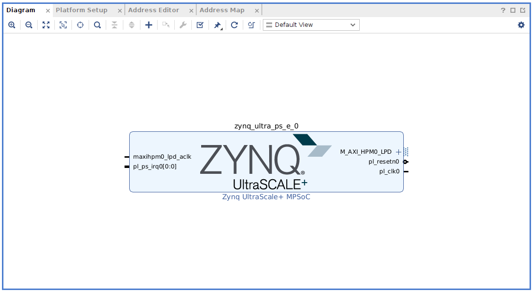
At this point, we have the PL ready. It will look like the one shown below.
The kernels to be executed on the FPGA side (PL) will need a clock. To make the design more configurable, we are going to add a Clocking Wizard.
This Clocking Wizard generates two different clocks running at 100 MHz and 200 MHz. This can be configured on the Output Clocks tab.
The kernels also need a reset, so we also add a Processor System Reset to generate a reset for each clock.
Finally, we need to add an AXI Initerrupt Controller.
In the AXI Interrupt Controller configuration, we have to change the Interrupt Output Connection from Bus to Single.
Then, by clicking on Run Connection Automation we are going to connect the AXI Interrupt Controller to the 200 MHz clock since this will be our default clock.
At this point, the block design is complete. It will be shown below.
A few months ago, in large block designs, I started to color the clock and the reset lines in order to be easily found in the block design, and I think that it is a good practice. To color some lines of your block design, you have to click in the gearbox located in the top-right of the block design and open the tab Colors.
Then changing the color of the Reset and Clock lines, the block design looks like the one shown below.
Now, in a regular design, we had finished with the block design, but in this design, we are going to create an Extensible Platform, so we need to configure the Extensible capabilities of our design. These extensible capabilities are the resources that the acceleration kernels will have.
First, we are going to define the available interfaces with the PS. On the top of the Block Design, we have an extra tab named Platform Setup, here we can configure the AXI interfafes available. We can select both all the FPD slave and master Interfaces of the PS. The slave interfaces are connected to the DDR, so they allow to send data from the kernel directly to the DDR, and the master interfaces are also connected to the DDR and allow to transfer data from the DDR to the kernel without using the processor.
Besides the interfaces connected directly to the PS, when we added the AXI Interrupt Controller, Vivado added an AXI Interconnect, so the interfaces of this AXI Interconnect are also available. I have enabled four of the master interfaces for the control of the kernels.
The next section is to enable the clocks available for the kernels. Both 100 Mhz and 200 Mhz will be enabled in this design, and we mark as default the 200 MHz clock.
The next sectio is for the interrupts. In this case we will use the intrc port of the AXI Interrupt Controller.
At this point the hardware design is complete. if we click on Validate Design, Vivado gives us a warning because the interrupt ports of the AXI Interrupt Controller are unconnected. We can ignore this warning.
Now we are going to generate the output products of the Block Design selecting Global in the Synthesis Options.
Once the output products are generated, we can use these output products to Export the Hardware, generate an xsa file to create a Petalinux project, and later generate the bitstream in Vitis. Since the way to install the applications on the Kria SOMs differs a little bit from the regular Zynq MPSOC, we are going to generate the bitstream in this step, and later create a Petalinux project with the xsa file complete.
To generate the bitstream, we need to generate the wrapper and then click on the Generate Bitstream.
When the bitstream is generated, we have to export the platform.
After clicking on Export Platform, a new window will be opened. First we need to select the type of the platform we are going to generate. Kria SOMs has no hardware model for emulation, so we need to export the platform just to be executed on real hardware.
Now we have to select the state of the platform. In our case the platform has a bitstream, so we need to check it, but we don’t want to export the post-implemented design since we want to allow Vitis change this design to include the acceleration kernels, so we need to check Pre-synthesis.
Now we have to give a name for the platform as well as a vendor name, version …
Finally, we will give a name for the xsa file.
At this point, we have the hardware ready to run Petalinux. In the next post, we are going to build a Petalinux compatible with this new hardware design, and will connect all of this with Vitis, where we will develop the accelerated application.


