Creating Pyhon driver for the AXI DMA IP

 ZUBoard
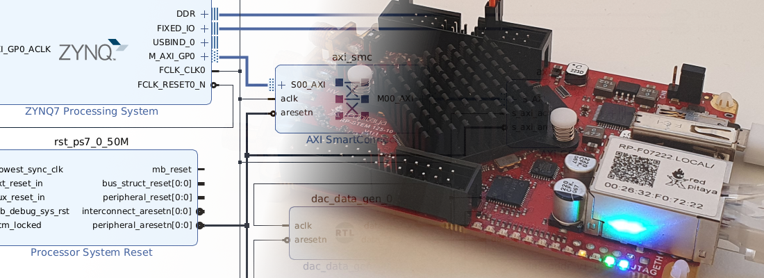
If someone asks me about the most useful peripheral of embedded systems, I do not doubt that the DMA (Direct Memory Access) is at my top. This is not just for Zynq devices, but from TI DSP, to Microchip devices, being able to move data from a peripheral, or an FPGA, to the DDR memory, without the need for the processor is something great. In fields like video processing, AI, or SDR (Software Defined Radio), DMA is a key element. In this article, we are going to dive into the AXI DMA, the AMD’s IP to manage the DMA of Zynq and Zynq MPSOC. We will design a driver that will allow us to manage DMA transactions from Petalinux using a driver written in Python.
First of all, of we want to allow the support for Python on Petalinux, we need to add some packages to the Petalinux build. Once the Petalinux project is created and configured, we need to navigate to /os/project-spec/meta-user/conf/user-rootfsconfig and add the next lines.
CONFIG_packagegroup-python3-jupyter
CONFIG_python3-mmap
These two packages will add python3 as well as different useful packages like jupyter-notebooks. Also, the package mmap will be added to allow Python to map the memory of the Zynq MPSOC. When these lines are added to the user-rootfsconfig file, we have to go to the rootfs configuration, and enable them under user-packages.
petalinux-config -c rootfs
At this point, we have our Petalinux ready to execute Python scripts.
When I am developing a Python script, I use a Jupyter Notebook to debug my code before releasing it. On Petalinux, what I used to do is launch a Jupyter server on the board, and then I access that server from my host computer. To do this, we need first to launch the Jupyter server.
zuboard-py:~$ sudo jupyter-notebook --allow-root --no-browser --ip=0.0.0.0
Since we need to be root to write and read directly from the memory, we need to execute the Jupyter server as root by adding the argument --allow-root. Also we need to tell Jupyter that we can not open a browser in this computer since we don’t have a screen, and finally, with the argument --ip=0.0.0.0 we are going to enable the remote access to the server.
OK, so now, we are inside our Petalinux under a Jupyter notebook so we can start developing our Python driver.
In the first place, we are going to declare all the addresses that we will use later. These addresses include the base address of the peripheral, which can be found in the Address Editor tab of the Vivado Block Design, and also the length of the peripheral reserved memory. Next, since we are going to move data from/to DDR memory, we also need to define both the source and the destination address. To define these addresses, the things turn more computistic. We need to note that the OS is using the memory, so we can’t write data in an address that is being used by the OS, we need to reserve memory ranges to be used by our applications, making the OS not see these memory ranges, and keep it empty. To reserve memory addresses, we need to modify the device tree of Petalinux (os/project-spec/meta-user/recipes-bsp/device-tree/files/system-user.dtsi) in order to add the node reserved-memory.
    reserved-memory {
       #address-cells = <2>;
       #size-cells = <2>;
       ranges;

       reserved: buffer@0 {
          no-map;
          reg = <0x0 0x0e000000 0x0 0x02000000>;
       };
    };

    reserved-mem@0 {
       compatible = "xlnx,reserved-memory";
       memory-region = <&reserved>;
    };
In this case, we are reserving from the address 0x0e000000 to the 0x10000000. Note that Zynq MPSOC features a 64-bit processor, so the addresses have to be defined for 64-bit memory, in groups of 32 bits. With the attribute no-map, the OS will not use this range.
Having all the memory addresses defined, we need to define the offsets of the peripheral’s registers. To check which configuration registers have the peripheral, we need to take a look to the product guide of the AXI DMA.
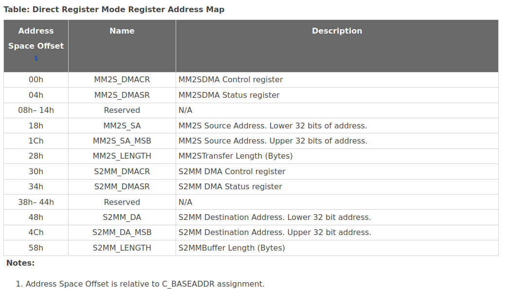
We can see that the registers are divided into two different groups, one of the for the communication from the DDR to the AXI Stream BUS (MM2S), and the other one from the AXI Stream to the DDR (S2MM). Each one with five registers.
We can also define the bits of the configuration register (DMCR), since we are going to use them to configure the peripheral.
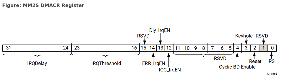
The final definition of all the addresses and register is the next.
# Registers definition

#### AXI DMA REGISTERS
AXI_DMA_BASE_ADDRESS = 0x80000000
AXI_DMA_SIZE = 0x10000

AXI_DMA_SRC_ADDRESS = 0x0e000000
AXI_DMA_DST_ADDRESS  = 0x0f000000

MM2S_CONTROL_REGISTER = 0x00
MM2S_STATUS_REGISTER = 0x04
MM2S_SRC_ADDRESS_REGISTER = 0x18
MM2S_TRNSFR_LENGTH_REGISTER = 0x28

S2MM_CONTROL_REGISTER = 0x30
S2MM_STATUS_REGISTER = 0x34
S2MM_DST_ADDRESS_REGISTER = 0x48
S2MM_BUFF_LENGTH_REGISTER = 0x58

IOC_IRQ_FLAG = 1<<12
IDLE_FLAG = 1<<1

# Config register definitions
HALT_DMA = 0x00000000
RUN_DMA = 0x00000001
RESET_DMA = 0x00000004
ENABLE_IOC_IRQ = 0x00001000
ENABLE_DELAY_IRQ = 0x00002000
ENABLE_ERR_IRQ = 0x00004000
ENABLE_ALL_IRQ = 0x00007000
In addition to the definition of the registers, and taking advantage of the Python’s features, I have defined a dictionary with all the possible states of the AXI DMA, so I will have a more verbose output.
# Status dictionary
dma_status_dict = {
    0x00000000 : "STATUS_RUNNING",
    0x00000001 : "STATUS_HALTED",
    0x00000002 : "STATUS_IDLE",
    0x00000004 : "STATUS_RSV",
    0x00000008 : "STATUS_SG_INCLDED",
    0x00000010 : "STATUS_DMA_INTERNAL_ERR",
    0x00000020 : "STATUS_DMA_SLAVE_ERR",
    0x00000040 : "STATUS_DMA_DECODE_ERR",
    0x00000080 : "STATUS_RSV",
    0x00000100 : "STATUS_SG_INTERNAL_ERR",
    0x00000200 : "STATUS_SG_SLAVE_ERR",
    0x00000400 : "STATUS_SG_DECODE_ERR",
    0x00000800 : "STATUS_RSV",
    0x00001000 : "STATUS_IOC_IRQ",
    0x00002000 : "STATUS_DELAY_IRQ",
    0x00004000 : "STATUS_ERR_IRQ"
}
Now, using the mmap package, we are going to map the different addresses we have defined before.
# Map the whole memory
f = os.open("/dev/mem", os.O_RDWR | os.O_SYNC)

print("Memory map the address of the DMA AXI IP via its AXI lite control interface register block.\n");
dma_virtual_addr = mmap.mmap(f, AXI_DMA_SIZE, flags=mmap.MAP_SHARED, prot=(mmap.PROT_READ | mmap.PROT_WRITE), offset=AXI_DMA_BASE_ADDRESS);

print("Memory map the MM2S source address register block.\n");
virtual_src_addr  = mmap.mmap(f, 0x10000, flags=mmap.MAP_SHARED, prot=(mmap.PROT_READ | mmap.PROT_WRITE), offset=AXI_DMA_SRC_ADDRESS)

print("Memory map the S2MM destination address register block.\n");
virtual_dst_addr  = mmap.mmap(f, 0x10000, flags=mmap.MAP_SHARED, prot=(mmap.PROT_READ | mmap.PROT_WRITE), offset=AXI_DMA_DST_ADDRESS)
In order to make easy write and read to the AXI DMA, I also have defined some generic functions for reading and writting to an AXI peripheral, and also two extra functions that return the AXI DMA status using the dictionary defined before.
# Write DMA register
def write_axi_register (virtual_addr, offset, value):

    virtual_addr.seek(offset) # move to the corresponding offset
    virtual_addr.write(struct.pack("=I", value)) #write data
    #virtual_addr.write(value.to_bytes(4, 'big')) #write data

    return 0

# Read DMA register
def read_axi_register (virtual_addr, offset):
    value = 0

    virtual_addr.seek(offset) # move to the corresponding offset

    #return struct.unpack('=I',virtual_dst_addr.read(4))[0]
    value = virtual_addr.read(4)

    return struct.unpack('=I',value)

# Read DMA S2MM Status
def read_dma_s2mm_status (virtual_addr):
    status = read_axi_register(virtual_addr,S2MM_STATUS_REGISTER)
    status_str = dma_status_dict[status[0] & 0x4FFF]
    return status_str

# Read DMA MM2SS Status
def read_dma_mm2s_status (virtual_addr):
    status = read_axi_register(virtual_addr, MM2S_STATUS_REGISTER)
    status_str = dma_status_dict[status[0] & 0x4FFF]
    return status_str
Now it is time to start the DMA configuration. The next lines are a set of instructions aimed to initialize the AXI DMA, and configure it with the corresponding source and destination addresses.
# Reset DMA
write_axi_register(dma_virtual_addr, S2MM_CONTROL_REGISTER, RESET_DMA)
write_axi_register(dma_virtual_addr, MM2S_CONTROL_REGISTER, RESET_DMA)

# Halt DMA
write_axi_register(dma_virtual_addr, S2MM_CONTROL_REGISTER, HALT_DMA)
write_axi_register(dma_virtual_addr, MM2S_CONTROL_REGISTER, HALT_DMA)

# Enable interrupts
write_axi_register(dma_virtual_addr, S2MM_CONTROL_REGISTER, ENABLE_ALL_IRQ)
write_axi_register(dma_virtual_addr, MM2S_CONTROL_REGISTER, ENABLE_ALL_IRQ)

# Write source address
write_axi_register(dma_virtual_addr, MM2S_SRC_ADDRESS_REGISTER, AXI_DMA_SRC_ADDRESS);

# Write destination address
write_axi_register(dma_virtual_addr, S2MM_DST_ADDRESS_REGISTER, AXI_DMA_DST_ADDRESS);
Once the DMA is configured, we can run both channels.
# Run the MM2S channel
write_axi_register(dma_virtual_addr, MM2S_CONTROL_REGISTER, RUN_DMA);
print(f'MM2S Status: {read_dma_mm2s_status(dma_virtual_addr)}')

# Run the S2MM channel.
write_axi_register(dma_virtual_addr, S2MM_CONTROL_REGISTER, RUN_DMA);
print(f'S2MM Status: {read_dma_s2mm_status(dma_virtual_addr)}')
Note that, at this point, the DMA is charged, but it is still waiting to start a transaction. Before triggering the DMA, I have filled 12 bytes in the source address.
# Write data
data = [0xDEADBEEF, 0x33001111, 0x22223333]

virtual_src_addr.seek(0)
virtual_src_addr.write(struct.pack("<3I", *data))
Now, we can trigger the DMA by writing the number of bytes we want to transmit. If we are testing the AXI DMA by creating a loop between the input and the output, we need to configure the length in both the transmitter and the receiver.
nbytes = 12

# Writing MM2S transfer length of n bytes...
write_axi_register(dma_virtual_addr, MM2S_TRNSFR_LENGTH_REGISTER, nbytes);
print(f'MM2S Status: {read_dma_mm2s_status(dma_virtual_addr)}')

# Writing S2MM transfer length of n bytes
write_axi_register(dma_virtual_addr, S2MM_BUFF_LENGTH_REGISTER, nbytes);
print(f'S2MM Status: {read_dma_s2mm_status(dma_virtual_addr)}')
time.sleep(1)
When the DMA finishes the operations (we can verify it by reading the status of the peripheral), we can read the destination address and check that, indeed, data has been written.
virtual_dst_addr.seek(0)
data_unpack = struct.unpack('=3I',virtual_dst_addr.read(nbytes))

for i in data_unpack:
    print(hex(i))
Creating our peripherals in Verilog to be used from a Linux OS is very powerful, but creating a high-level driver using Python multiplies the possibilities of the game. In this article, we have seen how to manage the AXI DMA peripheral using some Python packages, but this is not different from writing Python drivers for any other AXI peripheral. The functions write_axi_register or read_axi_register will allow us to write and read from the AXI bus in a generic way. Joining this to the DMA, we can create drivers for the data processing IP or video processing IP like the MIPI CSI-2 reception.