Creating a custom Petalinux image for RedPitaya STEMlab

 STEMlab 125-10
Some time ago, I wrote an article about how to create a custom hardware design for a RedPitaya STEMlab. Although the article was written in September 2023, things have changed a bit around Vivado and Petalinux. Since in that article I focused on the HW design, in this article I want to put the focus on the operating system design. However, this does not mean that we can start with the hardware design we developed on that article, we are going to start from zero, modifying several configurations of the HW design in order to have our Petalinux image running on the RedPitaya STEMlab.
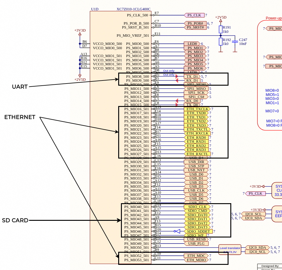
Since we are going to create a new project, this time for Vivado 2024.2, we need to download the board file from the RedPitaya GitHub repository. The repository we need is RedPitaya-FPGA. There, we can navigate until we find the board file, however, none of the peripherals are enabled in this file, so we need to do it manually. To know which peripherals we need to enable, and how to configure them, we need the schematics of the board, and the documentation. The STEMlab I have is the version 125 10, which is discontinued now, but the steps are the same if you have the newest board, actually, the board file is more related with the latest boards than the mine. In the schematics we can find the peripherals connected to the Zynq 7010 device, and also the MIO pins used. Another interesting point is the voltage of the power supply for the two banks (500 and 501) of the Processing System.
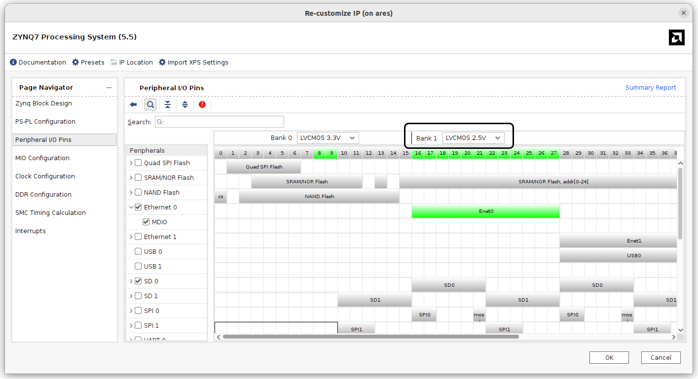
When we have all the peripherals located, we can create the Vivado project for the RedPitaya board file downloaded, create a block design with the processing system, and enable the corresponding peripherals in the correct MIO pins. Also notice that, by default, the bank voltages are configured to 3.3 V, however, the bank 1 of the board is connected to 2.5 V.
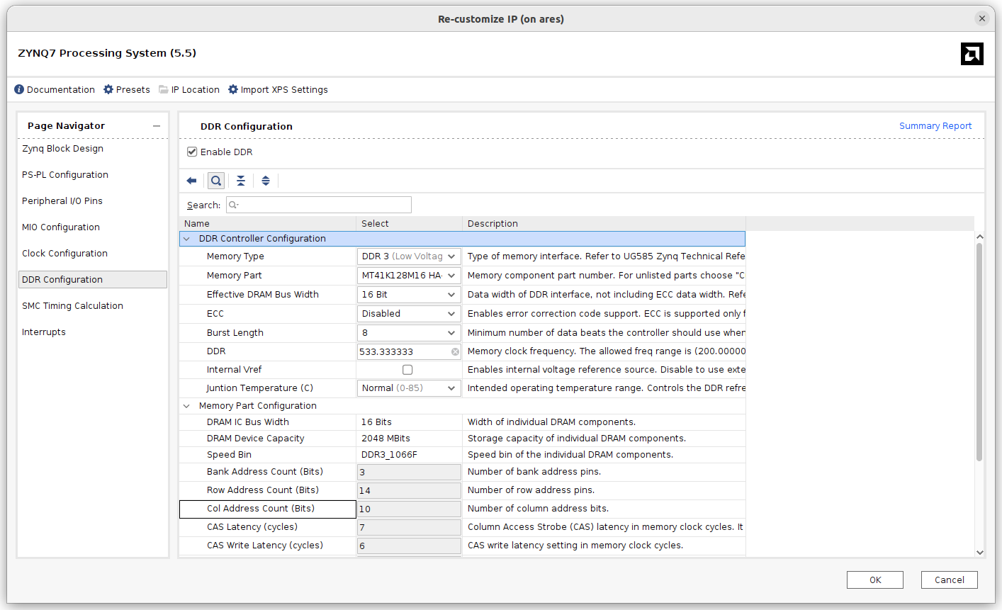
I mentioned before that the board file available in the Redpitaya GitHub repository is more related to the latest versions of the board. Those boards have a DDR memory of 512 MB (4 Gb), however the 125 10 variant only has 256 MB (2Gb). If you have the 125 14, you don’t need to make this change, but if you, like me, have the 125 10 variant, we need to change the DDR memory in the PS configuration.
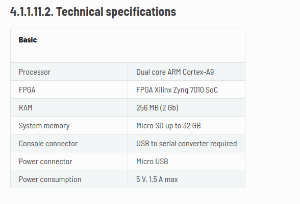
We only know that the features of the memory are 2Gb and 16 bits, so we are going to configure the DDR according to this data.
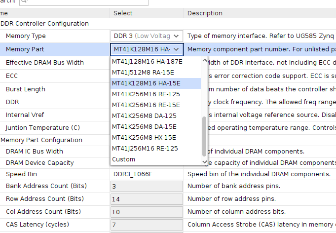
However, when we needed to select the memory part, some of them fit our requirements, so since we needed to choose one, I selected the MT41K128M16 HA-15E. I am not 100% sure that this is exactly the part on my board, but it is manufactured from the same vendor and has the same characteristics, so it has to work.
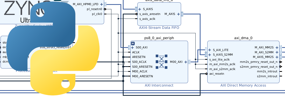
Once we have configured the processing system, I have added an AXI GPIO connected to the eight LEDs of the board to test the design. The final block design will be the next.
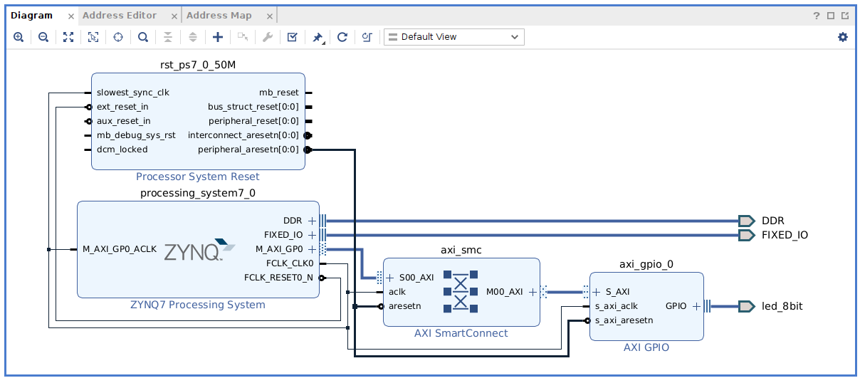
Now the hardware design is finished, so we need to generate the bitstream, and export the hardware including the bitstream in order to use it in the Petalinux image creation.
Now, from a Linux machine, we are going to start the Petalinux building. First, we need to create the Petalinux project. Then I also work with fixed folder names, being hw/ for the hardware design, and os/ for the Petalinux project, so I change the name of the folder with os/. Now we can configure the image and add the hardware design to the project.
~/redpitaya_custom$ petalinux-create --type project --template zynq --name redpitaya-custom
~/redpitaya_custom$ mv redpitaya-custom/ os/
~/redpitaya_custom$ cd os/
~/redpitaya_custom/os$ petalinux-config --get-hw-description ../hw
In the Petalinux configuration, we need to change the root filesystem type, and also we can disable the tftpboot, since it won’t be used.
Image packaging Configuration > Root filesystem type (EXT4 (SD/eMMC/SATA/USB))

[ ] Copy final images to tftpboot
Now, we are going to add some features to the Petalinux image. To add packages, we need to edit the user-rootfsconfig file.
~/redpitaya_custom/os$ nano project-spec/meta-user/conf/user-rootfsconfig
Here we are going to add the Jupyter notebooks, to edit and execute Python scripts from the browser, and also add some Python useful packages like mmap (to write over the AXI4 bus), and numpy (to make maths stuff).
#Note: Mention Each package in individual line
#These packages will get added into rootfs menu entry

CONFIG_gpio-demo
CONFIG_peekpoke
CONFIG_packagegroup-python3-jupyter
CONFIG_python3-numpy
CONFIG_python3-mmap
Once the packages are added to the configuration, we need to enable them by configuring the rootfs.
~/redpitaya_custom/os$ petalinux-config -c rootfs
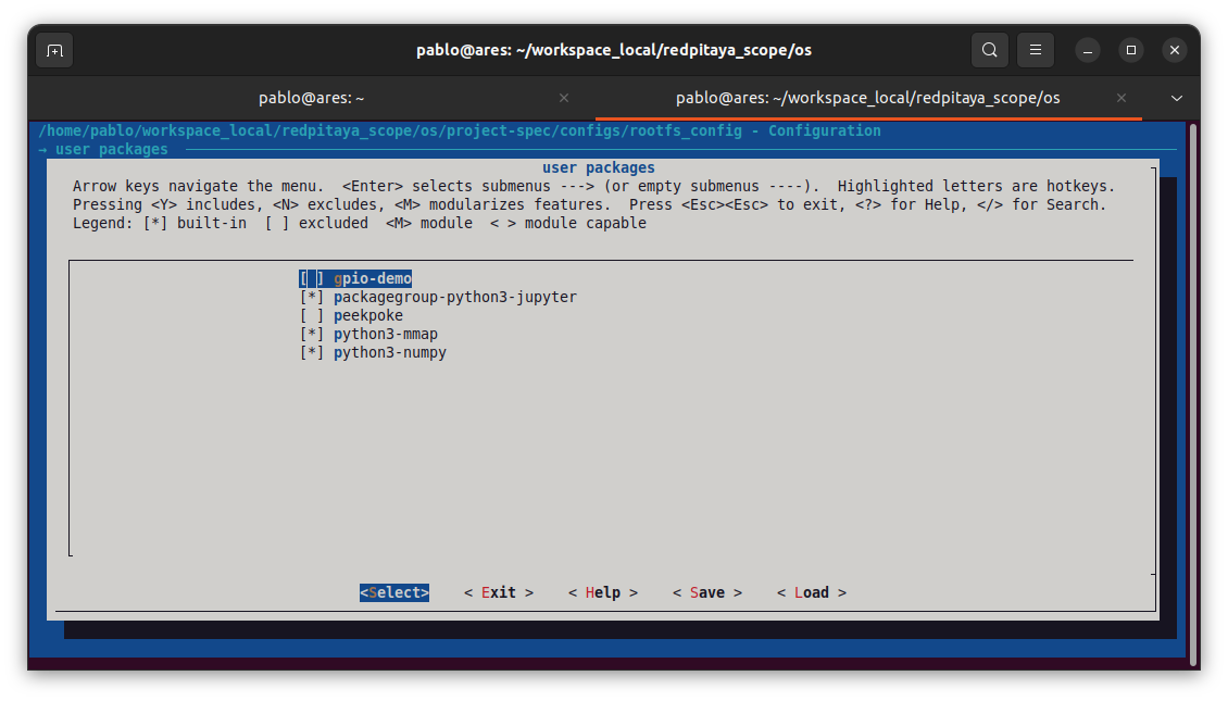
Once these packages are enabled, we can build the Petalinux image.
~/redpitaya_custom/os$ petalinux-build
When the build finishes, we need to generate the boot files.
~/redpitaya_custom/os$ cd images/linux/
~/redpitaya_custom/os/images/linux$ petalinux-package --boot --u-boot --fpga --force
When boot files are generated, we have two options, copy manually the files into the SD card, or generate a wic file and write it up into an SD card. This second option will generate the corresponding partitions in the SD card automatically. To generate the wic file we can do it with the petalinux-package command.
~/redpitaya_custom/os$ petalinux-package --wic
Finally, the wic file can be written into the SD card using Balena Etcher, or using the dd command from linux.
~/redpitaya_custom/os/images/linux$ sudo dd if=./petalinux-sdimage-wic of=/dev/sda bs=512M status=progress
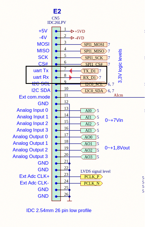
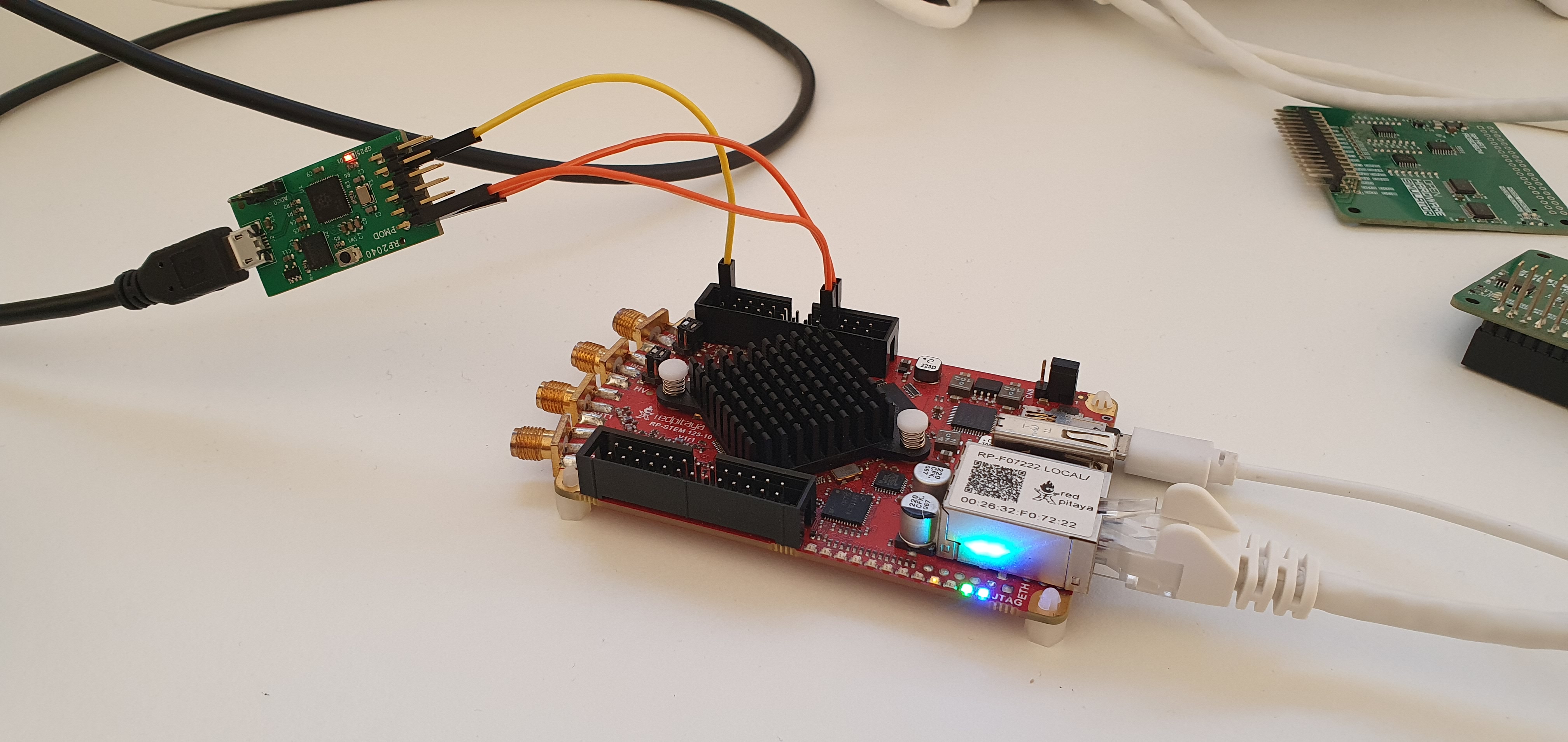
Once the SD card is ready, we can insert it into the board, and power up the board. Notice that the USB port of the STEMlab is used just for powering the board, and it is not connected to any serial interface. To be able to use the serial interface, we need to connect a serial to USB converter to the connector E2. In my case, I used the RP2040 PMOD with a code that generates two UART ports in the host.
My final setup is the next.
Now, we can see using any serial terminal the Petalinux boot. On the first boot, Petalinux will ask us to change the password. This password, is stored in the root filesystem, so since we have configured the root filesystem on the SD card, the password will be stored for the next boots.
Once we have the board ready, we can launch a jupyter-notebook. To be able of accesing to the jupyter server from the host computer, we need to add some arguments.
PetaLinux 2024.2+release-S11061705 redpitaya-custom ttyPS0

redpitaya-custom login: petalinux
Password:
redpitaya-custom:~$ sudo jupyter-notebook --no-browser --allow-root --ip=0.0.0.0
When Jupyter starts, it will give us a token, and a url where we can acces to the server.
[I 2018-03-09 12:36:18.940 ServerApp] http://127.0.0.1:8888/tree?token=d357e9f1e491ef9f950c016e0238e18afedc77d017854a17
The IP of the url is localhost, so in order to access from the host computer we need to replace 127.0.0.1 with 192.168.1.201 (or the IP given by our DHCP), and the Jupyter server will be accesible.
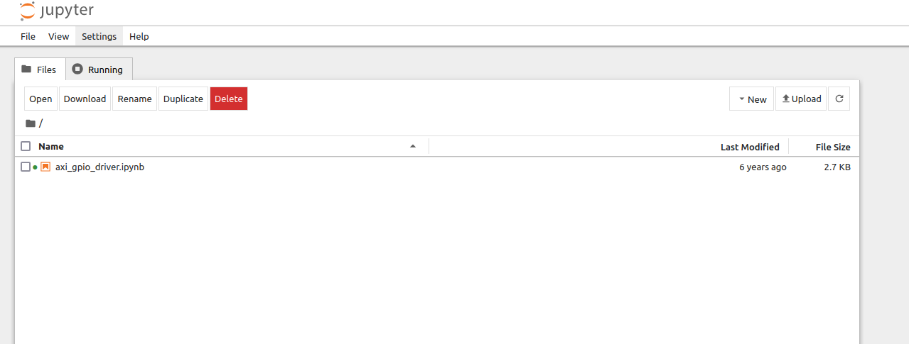
Here, we are going to create a new notebook. In this notebook we will create two generic functions to write and read AXI4 registers, and then use those functions to write in the AXI GPIO. The entire Python code is the next.
import os
import mmap
import struct
import time

#define AXI GPIO register space
AXI_GPIO_BASE_ADDRESS = 0x41200000
AXI_GPIO_SIZE = 0x10000
AXI_GPIO_DATA_OFFSET = 0x00
AXI_GPIO_TRI_OFFSET = 0x04

# generic functions
def write_axi_reg (peripheral, offset, value):
    peripheral.seek(offset)
    peripheral.write(struct.pack("=H", value))

def read_axi_reg (peripheral, length, offset):
    peripheral.seek(offset)
    return int.from_bytes(peripheral.read(length), "big")

# Open /dev/mem
devmem = os.open("/dev/mem", os.O_RDWR | os.O_SYNC)
axi_gpio = mmap.mmap(devmem, AXI_GPIO_SIZE,flags=mmap.MAP_SHARED, prot=(mmap.PROT_READ | mmap.PROT_WRITE), offset=AXI_GPIO_BASE_ADDRESS)

#write_axi_reg(axi_gpio, AXI_GPIO_DATA_OFFSET, 87) # Example for writting
#read_axi_reg(axi_gpio, 1, AXI_GPIO_DATA_OFFSET) # Example for reading
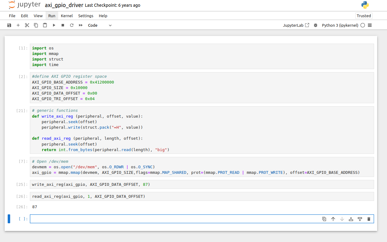
Using this code as a base code, you can create different drivers for the AMD’s AXI4 IP or for your own custom peripherals.
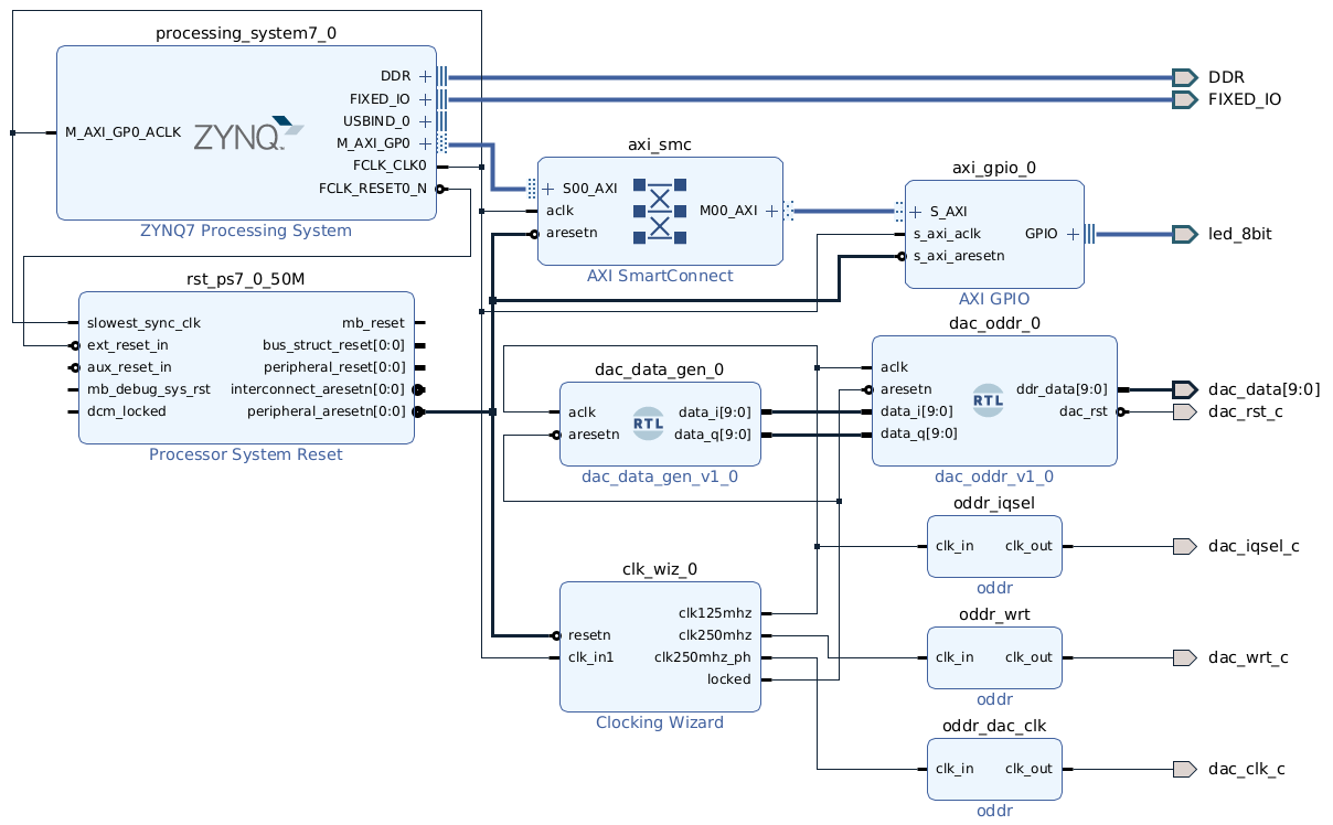
If you want to integrate the DAC of the board in your block design, here you have an example block design of the DAC driver.
Either for using it as portable lab instrumentation, or use it in a wild mode by creating your own design, the RedPitaya STEMlab is a great choice to create great things. The only thing I miss in this board, is an integrated JTAG, but it is not a big deal since Petalinux has included by default fpgautil, so we can update the FPGA design within the os.