Using the AXI DMA in Petalinux 2024.1
A year ago I wrote an article about how to use the AXI DMA peripheral within Petalinux. This article worked at the moment I wrote it but a year later, it stopped working. I am not 100% sure of the cause, but I think that it is related to the newest versions of the Linux kernel used in the latest Petalinux releases. Fortunately, I just needed a post on X to some users to recommend a different kernel driver, the u-dma-buf. This article is intended to be used as a guide about how to use this driver, and also, how to use it using Python and a Jupyter Notebook, without the need to use Pynq.
The article is divided into nine different points.
- Hardware Design
- Petalinux project
- Adding the kernel driver
- Configuring the device tree
- Adding the Python package
- Building Petalinux
- Booting the ZUBoard
- Testing the AXI DMA driver with Python
- Conclusions
Hardware Design
First of all, we are going to create the hardware design. In order to keep a standard file tree, we are going to create a folder for the project, and inside this folder we will create the /hw folder. This folder will be use to store the Vivado project. In Linux, we can do this using the command mkdir.
pablo@ares:~/workspace_local/zuboard_dma$ mkdir hw
Now, we are going to open Vivado. In Linux, we need first to execute the settings.sh script in order to add the environment variables. Then we can execute vivado in the terminal to open Vivado.
pablo@ares:~/workspace_local/zuboard_dma$ source /mnt/data/xilinx/Vivado/2024.1/settings64.sh
pablo@ares:~/workspace_local/zuboard_dma$ vivado
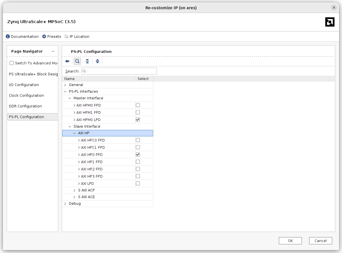
Once in Vivado, we will create a Block Design. In this Block Design, we will add the Processing System (PS), and then click on Run Block Automation. Be sure the Apply Board Preset tick is checked in order to configure the DDR and the peripherals included in the ZUBoard. In the PS configuration, since we are going to use the DMA, we need to enable the AXI HP0 FPD slave interface, and also a master AXI interface to configure the AXI DMA IP, in my case I have enabled the AXI HPM0 LPD.
With these interfaces enabled we can add the axi_dma IP, and let Vivado connect it to the corresponding interfaces. As a AXI Stream peripherals, I have used an AXI4-Stream Data FIFO. The complete Block Design looks as the next.

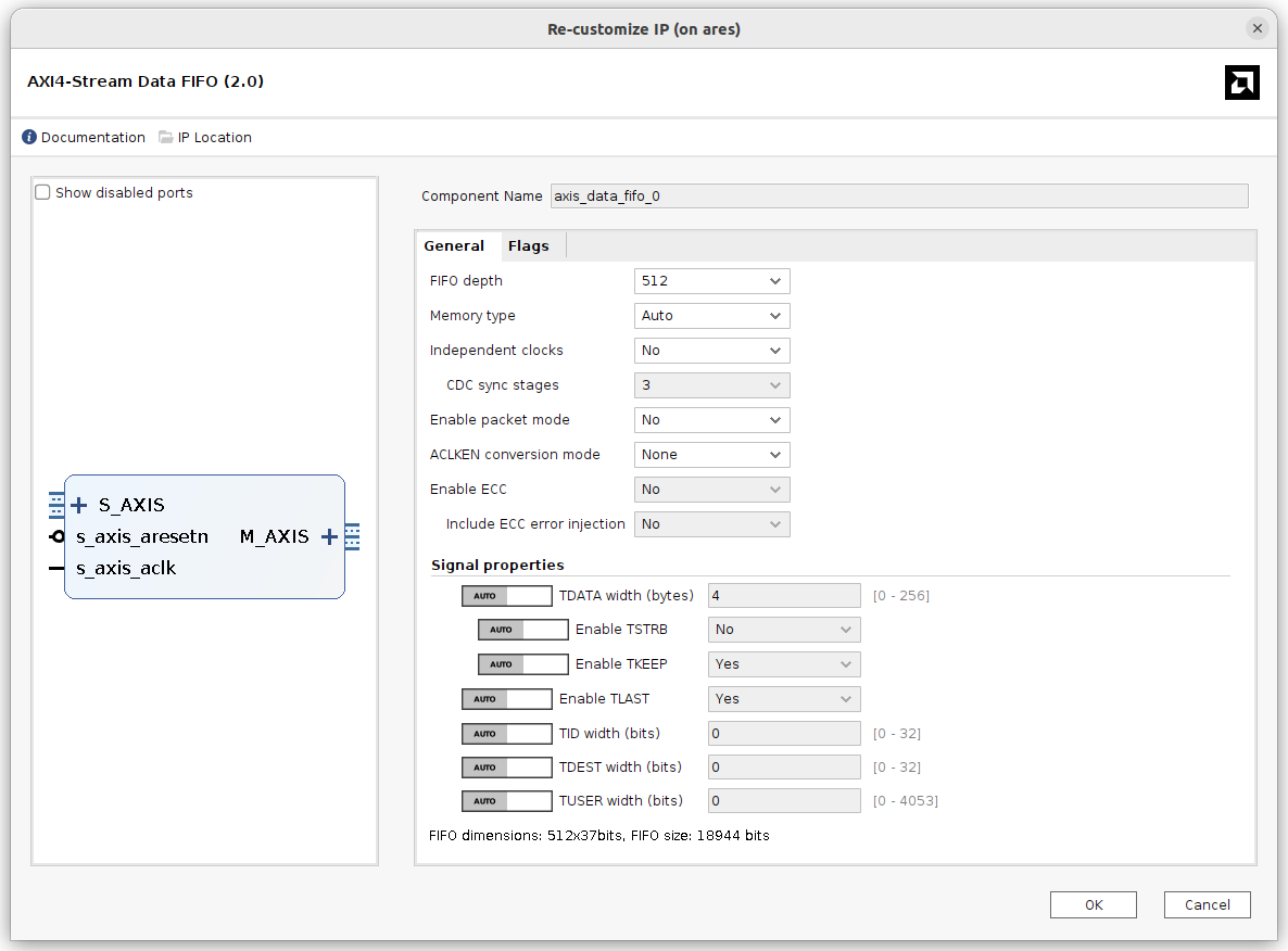
Regarding the FIFO configuration, I have configured a depth of 512 words of 32 bits (this width is configured automatically according to the width of the AXI4-Stream interface), and the rest of the configuration is configured by default.
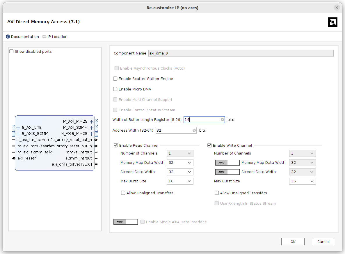
For the AXI DMA IP, I have disabled the Scatter Gather Engine, and the rest of the options will remain as default.
Now, we can create the wrapper, generate the bitstream and finally export the hardware to generate the .xsa file which will be used in the Petalinux build step.
Petalinux project
With the hardware design ready, we are going now to generate the Petalinux distribution for this project. First of all, we are going to add the Petalinux environment variables to the PATH. This can be done by executing the script settings64.sh located in the Petalinux installation directory.
Now, we will navigate to the project folder, and here we can create a new Petalinux project with the name zuboard_dma.
pablo@ares:~/workspace_local/zuboard_dma$ petalinux-create --type project --template zynqMP --name zuboard_dma
As we did with the hardware project, which is inside the /hw folder, the Petalinux project will be located in a folder named /os. Since in the step where the Petalinux project is generated it also generates a folder with the name of the project, we just need to rename that folder to /os
pablo@ares:~/workspace_local/zuboard_dma$ mv ./zuboard_dma ./os
pablo@ares:~/workspace_local/zuboard_dma$ cd ./os
Now, navigate to the new /os folder, and execute the petalinux-config with the argument --get-hw-description command to link the hardware project to the Petalinux project.
pablo@ares:~/workspace_local/zuboard_dma/os$ petalinux-config --get-hw-description ../hw
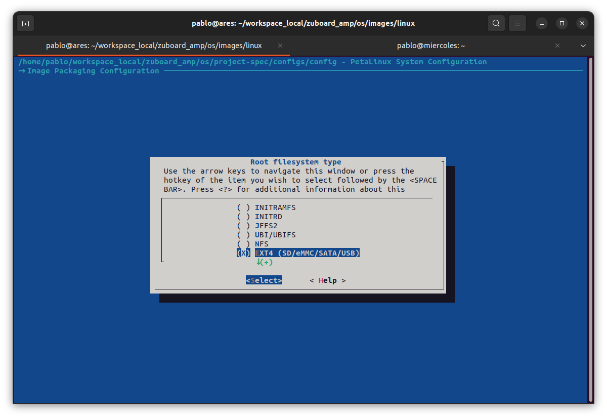
In the configuration window, we need to navigate to Image Packaging Configuration > Root file system type. Here, we will change the configuration to EXT4 (SD/eMMC/SATA/USB)
Now, we need to add to the device-tree a node for the SD card, but this will be done before.
Adding the kernel driver
As I mentioned before, the DMA is managed from the Linux kernel, so, if we want to manage it from the user-space, we need to add first a kernel module to generate a peripheral, and then use this peripheral from the user space. AMD gives us the dma_proxy driver, but it does not work in the newest Petalinux versions, at least in the same way as it worked before, so this time we are going to use a different driver, the u-dma-buf from KAWAZOME Ichiro. First, we need to add a new kernel module with the name u-dma-buf.
pablo@ares:~/workspace_local/zuboard_dma/os$ petalinux-create --type modules --name u-dma-buf --enable
Then, we have to change the default u_dma_buf.c file with the u-dma-buf.c from the repository, and the same for the Makefile
pablo@ares:~/workspace_local/zuboard_dma/os/project-spec/meta-user/recipes-modules/u-dma-buf/files$ gedit ./u-dma-buf.c
With these two files replaced, we can now go to add the device tree nodes.
Configuring the device tree
In order to connect the axi_dma IP to the new kernel driver added, we need to modify the file system-conf-dtsi.
pablo@ares:~/workspace_local/zuboard_dma/os$ nano ./project-spec/meta-user/recipes-bsp/device-tree/files/system-conf-dtsi
In this file, first we are going to add the udmabuf@0x00 to configure the driver. Information about the different options can be found in the readme of the u-dma-buf project. Now, we need to modify the node &axi_dma_0 to overwrite the compatible field.
Also, in this file we need to add the &sdhci0 node, which configures the SDIO peripheral, in charge of the interface with the SD card, and modify some fields. The resulting system-conf-dtsi is the next.
/include/ "system-conf.dtsi"
/ {
udmabuf@0x00 {
        compatible = "ikwzm,u-dma-buf";
        device-name = "udmabuf0";
        minor-number = <0>;
        size = <0x4000000>;
        sync-mode = <1>;
        sync-always;
	};

};


&axi_dma_0{
    	compatible = "generic-uio";
};

&sdhci0 {
	no-1-8-v;
	disable-wp;
};
Adding the Python package
Unlike the dma_proxy driver, where AMD provides an example application, in this case we are going to develop our test application using Python. To add Python to the Petalinux distribution, we have several options. The first one is to modify the Root File System using the petalinux-config -c rootfs command, and navigate to Filesystem Packages > misc > python3 > python3 to enable it.
pablo@ares:~/workspace_local/zuboard_dma/os$ petalinux-config -c rootfs
This configuration will only add to Petalinux Python3, but maybe we need to add also some packages. In this case, what I recommend is to take a look at the packages groups, and check if there is any of them that include all what we need.
To add Python3 to Petalinux we have several packages groups like packagegroup-petalinux-python-modules, and this is the one I wanted to use, but then I saw the packagegroup-petalinux-jupyter, that besides Python3 and several packages, also adds Jupyter notebooks to Petalinux so, what about to have something pretty similar to Pynq in a custom Petalinux distribution?
In order to add a package group, we can execute the petalinux-config -c rootfs command, and search this package group but, I can save you some time, this package can not be added using this menu, so we need to add it manually. This can be done modifying the file user-rootfsconfig, and adding to the end the line CONFIG_packagegroup-petalinux-jupyter.
pablo@ares:~/workspace_local/zuboard_dma/os/project-spec/meta-user/conf$ gedit user-rootfsconfig
The final user-rootfsconfig will look like the next. Notice that the u-dma-buf is already added.
#Note: Mention Each package in individual line
#These packages will get added into rootfs menu entry

CONFIG_gpio-demo
CONFIG_peekpoke
CONFIG_u-dma-buf
CONFIG_packagegroup-petalinux-jupyter
At this point all the configurations are done.
Building Petalinux
The next is to build our Petalinux distribution with the command petalinux-build.
pablo@ares:~/workspace_local/zuboard_dma/os/$ petalinux-build
When Petalinux is built, we need to generate the boot files, and remember to add the --fpga argument to add the bitstream.
pablo@ares:~/workspace_local/zuboard_dma/os/$ cd ./images/linux
pablo@ares:~/workspace_local/zuboard_dma/os/images/linux$ petalinux-package --boot --u-boot --fpga
When the BOOT.BIN file is generated, we can create the corresponding partitions in the SD Card, and copy and unzip the corresponding files… or we can just generate the wic file, which will generate an image file. To generate the wic file, we need to execute the command petalinux-package with the argument --wic.
pablo@ares:~/workspace_local/zuboard_dma/os/$ petalinux-package --wic
If you are using Linux, you can send to the SD Card the WIC file using the command dd. For the Windows users, you can use Balena Etcher or other similar application.
pablo@ares:~/workspace_local/zuboard_dma/os/$ sudo dd if ./images/linux/petalinux-sdcard.wic of=/dev/sda bs=1M status=progress
Once the SD card is generated, we can go to the board, insert the SD card, and boot the board.
Booting the ZUBoard
In the Linux boot process, you will see that the u-dma-buf driver is installed.

Once Linux boots, listing the devices, you will see a device named u-dma-buf. This is the DMA device that we will use to read and write data to the AXI DMA IP. Notice that is the same peripheral for both read and write, unlike the xDMA drivers used in this article, where different devices were generated to read and write.
zuboarddma:/usr/share/example-notebooks$ ls /dev
autofs ptyda ptytc ptyze ttya1 ttyq3 ttyw5
block ptydb ptytd ptyzf ttya2 ttyq4 ttyw6
btrfs-control ptydc ptyte ram0 ttya3 ttyq5 ttyw7
bus ptydd ptytf ram1 ttya4 ttyq6 ttyw8
char ptyde ptyu0 ram10 ttya5 ttyq7 ttyw9
console ptydf ptyu1 ram11 ttya6 ttyq8 ttywa
disk ptye0 ptyu2 ram12 ttya7 ttyq9 ttywb
dma_heap ptye1 ptyu3 ram13 ttya8 ttyqa ttywc
fd ptye2 ptyu4 ram14 ttya9 ttyqb ttywd
fpga0 ptye3 ptyu5 ram15 ttyaa ttyqc ttywe
full ptye4 ptyu6 ram2 ttyab ttyqd ttywf
gpiochip0 ptye5 ptyu7 ram3 ttyac ttyqe ttyx0
gpiochip1 ptye6 ptyu8 ram4 ttyad ttyqf ttyx1
hugepages ptye7 ptyu9 ram5 ttyae ttyr0 ttyx2
i2c-0 ptye8 ptyua ram6 ttyaf ttyr1 ttyx3
iio:device0 ptye9 ptyub ram7 ttyb0 ttyr2 ttyx4
initctl ptyea ptyuc ram8 ttyb1 ttyr3 ttyx5
kmsg ptyeb ptyud ram9 ttyb2 ttyr4 ttyx6
log ptyec ptyue random ttyb3 ttyr5 ttyx7
loop-control ptyed ptyuf rfkill ttyb4 ttyr6 ttyx8
loop0 ptyee ptyv0 rtc ttyb5 ttyr7 ttyx9
loop1 ptyef ptyv1 rtc0 ttyb6 ttyr8 ttyxa
loop2 ptyp0 ptyv2 shm ttyb7 ttyr9 ttyxb
loop3 ptyp1 ptyv3 snd ttyb8 ttyra ttyxc
loop4 ptyp2 ptyv4 stderr ttyb9 ttyrb ttyxd
loop5 ptyp3 ptyv5 stdin ttyba ttyrc ttyxe
loop6 ptyp4 ptyv6 stdout ttybb ttyrd ttyxf
loop7 ptyp5 ptyv7 tty ttybc ttyre ttyy0
mem ptyp6 ptyv8 tty0 ttybd ttyrf ttyy1
mmcblk0 ptyp7 ptyv9 tty1 ttybe ttys0 ttyy2
mmcblk0p1 ptyp8 ptyva tty10 ttybf ttys1 ttyy3
mmcblk0p2 ptyp9 ptyvb tty11 ttyc0 ttys2 ttyy4
mqueue ptypa ptyvc tty12 ttyc1 ttys3 ttyy5
net ptypb ptyvd tty13 ttyc2 ttys4 ttyy6
null ptypc ptyve tty14 ttyc3 ttys5 ttyy7
port ptypd ptyvf tty15 ttyc4 ttys6 ttyy8
pps0 ptype ptyw0 tty16 ttyc5 ttys7 ttyy9
ptmx ptypf ptyw1 tty17 ttyc6 ttys8 ttyya
ptp0 ptyq0 ptyw2 tty18 ttyc7 ttys9 ttyyb
pts ptyq1 ptyw3 tty19 ttyc8 ttysa ttyyc
ptya0 ptyq2 ptyw4 tty2 ttyc9 ttysb ttyyd
ptya1 ptyq3 ptyw5 tty20 ttyca ttysc ttyye
ptya2 ptyq4 ptyw6 tty21 ttycb ttysd ttyyf
ptya3 ptyq5 ptyw7 tty22 ttycc ttyse ttyz0
ptya4 ptyq6 ptyw8 tty23 ttycd ttysf ttyz1
ptya5 ptyq7 ptyw9 tty24 ttyce ttyt0 ttyz2
ptya6 ptyq8 ptywa tty25 ttycf ttyt1 ttyz3
ptya7 ptyq9 ptywb tty26 ttyd0 ttyt2 ttyz4
ptya8 ptyqa ptywc tty27 ttyd1 ttyt3 ttyz5
ptya9 ptyqb ptywd tty28 ttyd2 ttyt4 ttyz6
ptyaa ptyqc ptywe tty29 ttyd3 ttyt5 ttyz7
ptyab ptyqd ptywf tty3 ttyd4 ttyt6 ttyz8
ptyac ptyqe ptyx0 tty30 ttyd5 ttyt7 ttyz9
ptyad ptyqf ptyx1 tty31 ttyd6 ttyt8 ttyza
ptyae ptyr0 ptyx2 tty32 ttyd7 ttyt9 ttyzb
ptyaf ptyr1 ptyx3 tty33 ttyd8 ttyta ttyzc
ptyb0 ptyr2 ptyx4 tty34 ttyd9 ttytb ttyzd
ptyb1 ptyr3 ptyx5 tty35 ttyda ttytc ttyze
ptyb2 ptyr4 ptyx6 tty36 ttydb ttytd ttyzf
ptyb3 ptyr5 ptyx7 tty37 ttydc ttyte ubi_ctrl
ptyb4 ptyr6 ptyx8 tty38 ttydd ttytf udev_network_queue
ptyb5 ptyr7 ptyx9 tty39 ttyde ttyu0 udmabuf0
ptyb6 ptyr8 ptyxa tty4 ttydf ttyu1 uio0
ptyb7 ptyr9 ptyxb tty40 ttye0 ttyu2 uio1
ptyb8 ptyra ptyxc tty41 ttye1 ttyu3 uio2
ptyb9 ptyrb ptyxd tty42 ttye2 ttyu4 uio3
ptyba ptyrc ptyxe tty43 ttye3 ttyu5 urandom
ptybb ptyrd ptyxf tty44 ttye4 ttyu6 vcs
ptybc ptyre ptyy0 tty45 ttye5 ttyu7 vcs1
ptybd ptyrf ptyy1 tty46 ttye6 ttyu8 vcs2
ptybe ptys0 ptyy2 tty47 ttye7 ttyu9 vcs3
ptybf ptys1 ptyy3 tty48 ttye8 ttyua vcs4
ptyc0 ptys2 ptyy4 tty49 ttye9 ttyub vcs5
ptyc1 ptys3 ptyy5 tty5 ttyea ttyuc vcs6
ptyc2 ptys4 ptyy6 tty50 ttyeb ttyud vcsa
ptyc3 ptys5 ptyy7 tty51 ttyec ttyue vcsa1
ptyc4 ptys6 ptyy8 tty52 ttyed ttyuf vcsa2
ptyc5 ptys7 ptyy9 tty53 ttyee ttyv0 vcsa3
ptyc6 ptys8 ptyya tty54 ttyef ttyv1 vcsa4
ptyc7 ptys9 ptyyb tty55 ttyp0 ttyv2 vcsa5
ptyc8 ptysa ptyyc tty56 ttyp1 ttyv3 vcsa6
ptyc9 ptysb ptyyd tty57 ttyp2 ttyv4 vcsu
ptyca ptysc ptyye tty58 ttyp3 ttyv5 vcsu1
ptycb ptysd ptyyf tty59 ttyp4 ttyv6 vcsu2
ptycc ptyse ptyz0 tty6 ttyp5 ttyv7 vcsu3
ptycd ptysf ptyz1 tty60 ttyp6 ttyv8 vcsu4
ptyce ptyt0 ptyz2 tty61 ttyp7 ttyv9 vcsu5
ptycf ptyt1 ptyz3 tty62 ttyp8 ttyva vcsu6
ptyd0 ptyt2 ptyz4 tty63 ttyp9 ttyvb vfio
ptyd1 ptyt3 ptyz5 tty7 ttypa ttyvc vhci
ptyd2 ptyt4 ptyz6 tty8 ttypb ttyvd watchdog
ptyd3 ptyt5 ptyz7 tty9 ttypc ttyve watchdog0
ptyd4 ptyt6 ptyz8 ttyPS0 ttypd ttyvf watchdog1
ptyd5 ptyt7 ptyz9 ttyS0 ttype ttyw0 zero
ptyd6 ptyt8 ptyza ttyS1 ttypf ttyw1
ptyd7 ptyt9 ptyzb ttyS2 ttyq0 ttyw2
ptyd8 ptyta ptyzc ttyS3 ttyq1 ttyw3
ptyd9 ptytb ptyzd ttya0 ttyq2 ttyw4
Since we have a device that we can use to send and receive data, we can use the command dd to write and read. Although this is possible, it is not the most common way to use this kind of device. Instead of that, we are going to develop an application.
Testing the AXI DMA driver with Python
To develop the application to manage the AXI DMA IP, we are going to use Python3 through a Jupyter Notebook. In order to see the Jupyter Notebook in the browser of the host, we can use the port 80 of the board to access, or we can redirect the port 80 of the board to the 8080 of the host, and this is what I am going to do. First, we need to connect to the board through SSH adding the argument 8080:localhost:8080.
$ ssh -L 8080:localhost:8080 [email protected]
Then, we will execute the jupyter-notebook command with the arguments --no-browser, --port=8080 and --allow-root. This will execute the server in the port 8080, and it will work in a no-browser mode.
zuboarddma:~$ sudo jupyter-notebook --no-browser --port=8080 --allow-root

We trust you have received the usual lecture from the local System
Administrator. It usually boils down to these three things:

    #1) Respect the privacy of others.
    #2) Think before you type.
    #3) With great power comes great responsibility.

For security reasons, the password you type will not be visible.

Password:
Now, from the host computer, we can open the Internet browser, and navigate to localhost:8080 to open the server.
The Python code we will use is the next. In the application, first we open the device /dev/udmabuf0 with the read/write mode. Then, we are going to generate an array of 100 elements using the linspace command. Next, we need to convert to integers the values of the array, and package it in groups of four bytes, to create 32-bit values. Finally, with the command os.pwrite and os.pread we can read and write to/from the device.
import os
import struct
import numpy as np

# Open the DMA device
dma_axis_rw_data = os.open("/dev/udmabuf0", os.O_RDWR)

# Create a data array
nsamples = 100
samples = np.linspace(0,1000,nsamples)
samples_int = samples.astype('int')

# Send data through DMA
data = struct.pack('<100Q', *samples_int)
os.pwrite(dma_axis_rw_data,data,0)

# Read data through DMA
data_rd = os.pread(dma_axis_rw_data,800,0)
data_unpack = struct.unpack('<100Q',data_rd)

# Check result
result = 1

for i in range(0,len(samples_int)):
    if (samples_int[i] != data_unpack[i]):
        result = 0

if (result):
    print("Test finished succesfully!")
else:
    print("Test Failed")
The code in the end of the script just verify that the data sent is the same as the data written.
Conclusions
The power of the devices that combine a CPU and an FPGA is limitless and features like the one explained in this article, the capability to send and receive big amounts of data between the CPU and the FPGA is one of the reasons for that. From Artificial Intelligence to Digital Signal Processing, this article can be the base of all those applications but, remember, great power requires a big responsibility, so be careful.
This is the last article of the year so, Merry Christmas and Happy New Year, and I hope that Santa and SSMM Los Reyes Magos bring you many FPGA gifts!


